perating and Installation
digital lines that can serve as alarm sensing or pulse
Four of the lines are available on four 2
pin MTA connectors J7, J9, J11 and J12, as shown
. These are normally used as alarm
sensing inputs and are often prewired for specific
alarm triggers such as a magnetic TAMPER switch.
However any of these can be configured
Two other lines are available on the “TB4” terminal block. These are most often used as pulse
counting inputs but can also be configured as alarm
A), normally closed (Form
B) or combined into a KYZ
C connections there are certain lines that can be
can be used to control external equipment from the central office
light, an audio alarm or a pump (remote control of this output is only available when using the
data collection system). Or it can be configured as a “repeater”, replicating
that is configured as an input
An output has strict limitations with respect to voltage and current.
See the specifications section to avoid damage to the
An “alarm” is an event such as a switch closing or opening.
The CNI2 reports the alarm
ition to the data collection system (
) using standard descriptions as
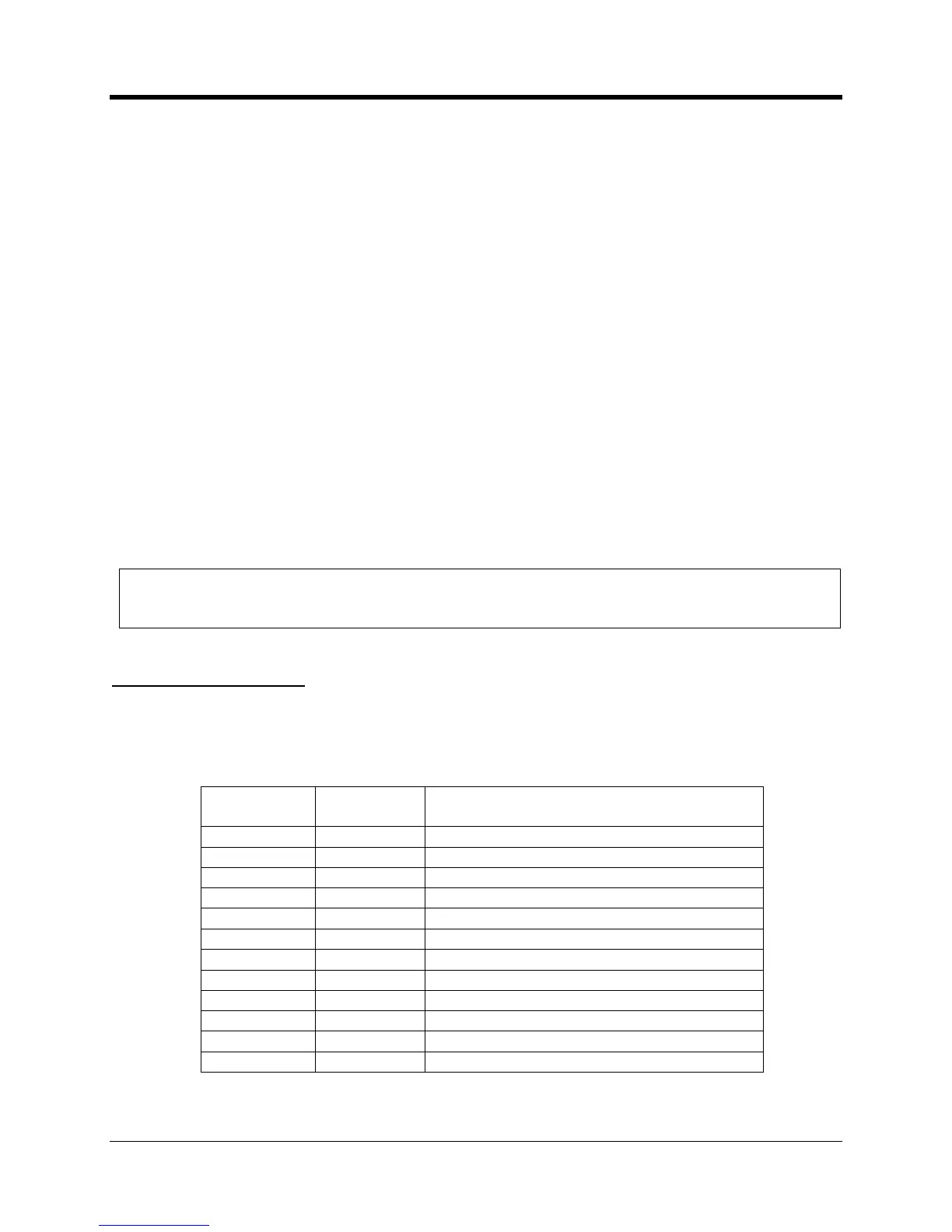
Alarm Text Reported by DC2009
Standard Alarm Descriptions

 Loading...