perating and Installation
” input is usually connected to a magnetic switch located inside the unit. You can
activate the switch by placing a stro
ng magnet near this spot on the outside of the enclosure.
Alternatively the switch can be a simple pushbutton switch located inside the unit or protruding
from the wall of the enclosure. Or you can just momentarily short the J9 pins with a screwdriver
coin. This switch will cause the CNI2 to immediately call in to the central computer and report
a “Call” or “Mag. Switch’ alarm.
” switch is often a magnetic switch mounted to the side of the enclosure and a
magnet on the door. When the door
is opened the magnet and switch separate and generate
an alarm. This is often used to detect intrusion as well as record service events.
If you wish to use these inputs for any other purpose you can rename them in the data collection
ce you could rename the “Tamper” alarm as “Low Pressure” or “High
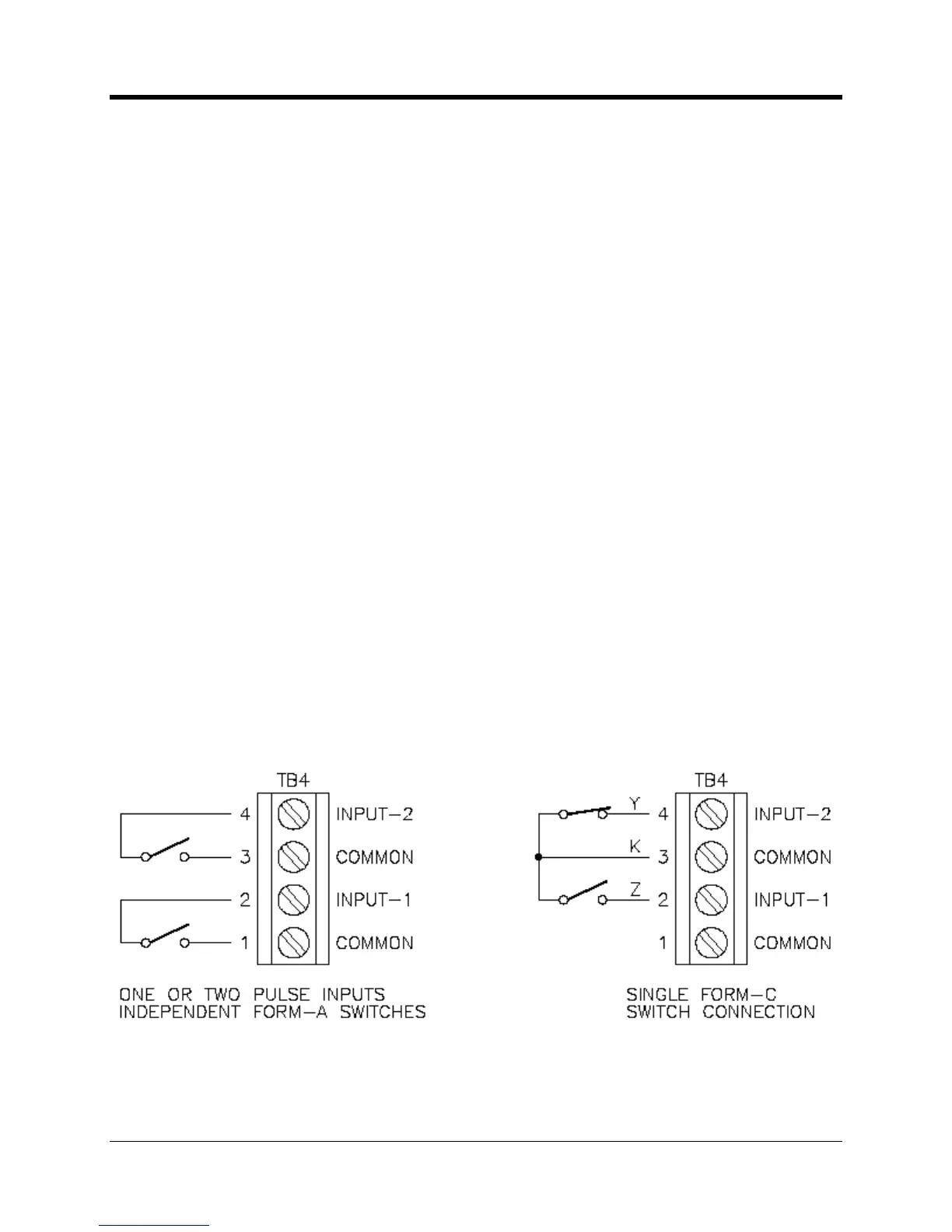
You can also combine the “Call” and “Tamper” inputs together as a Form
which case the combination is reported as a “Call” alarm to the data collection syste
C switch consists of one normally
closed switch. If at any time
both are open or closed this is considered a failure and will be reported as a “Tamper” alarm.
The “Power Fail” input is usually used to detect the loss of
ac mains power. When the alarm
goes active this will be reported as an “AC
OFF” alarm. When it returns to an inactive state an
ON” alarm will be reported. Again if you wish to use this input for any other purpose you
can rename it in the data coll
In many standard configurations the J7 “Alarm” input can also be used as an alarm or pulse
counting input. This input is not reported to the system as any particular alarm but the CNI2 can
still call in immediately if this input goes act
ive or inactive. Usually if this line is programmed as
an input it is used for pulse
counting rather than an alarm.
Alarm / Pulse Input Terminal Block TB4

 Loading...