perating and Installation
Besides processing alarms and pulse data the
can act as a “transparent” modem. This
central computer to communicate directly with a device connected to the
232 serial port. An option board called the Dual Port Multiplexer allows a second port to be
added. Future expansion boards will offer even more ports.
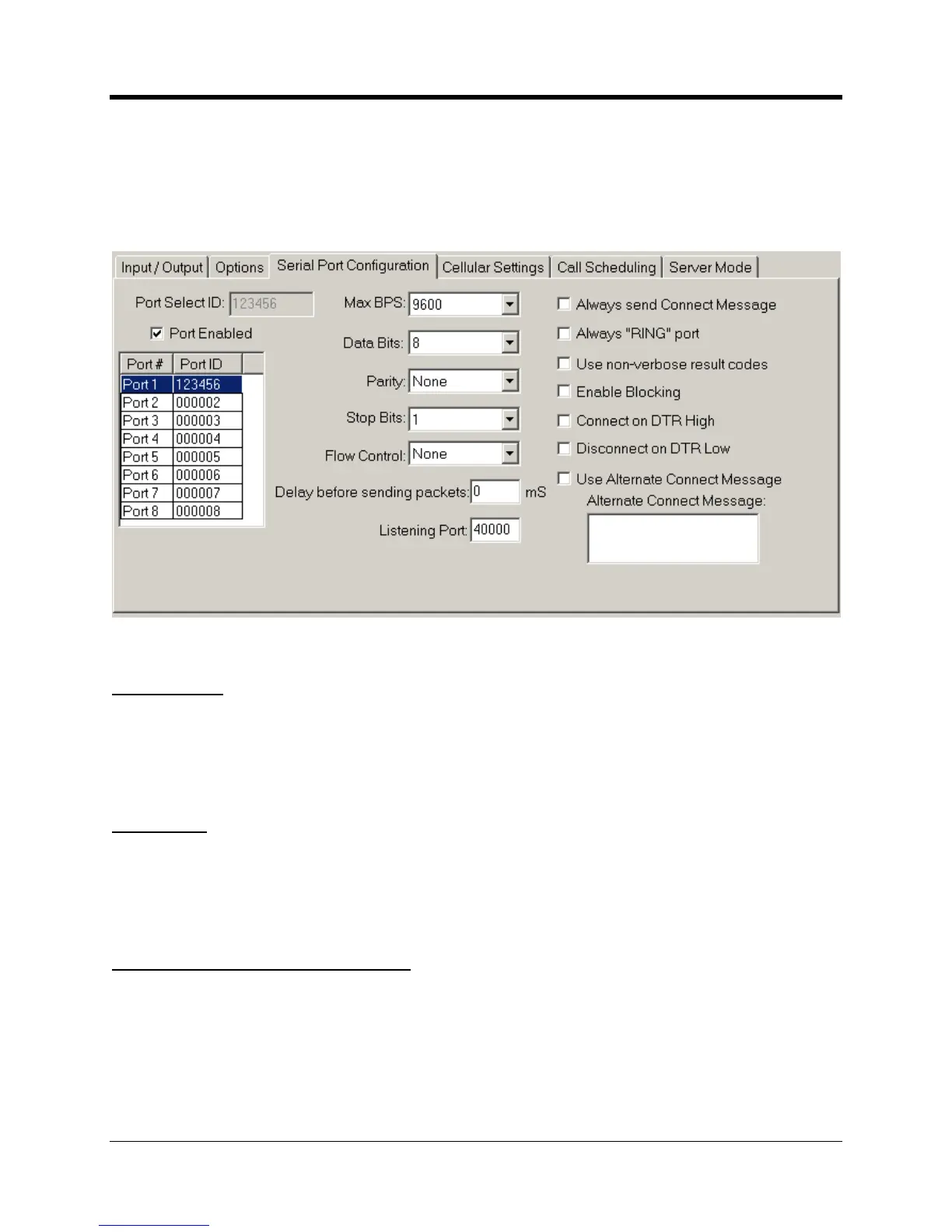
Each serial port must be assigned a unique
number. The format follows that of
the Primary RUID discussed earlier. Serial Port
1 is the physical port TB2 on the
Primary RUID. Its Port Select ID is grayed out and cannot be
box to turn on a serial port.
Ports must be enabled in ascending order
1 is enabled, and then you skip
this will automatically enable Ports
2 and 3 as well. Conversely if Ports 1 thru 4 are enabled
2, this will automatically disable Ports
Max BPS. Data Bits, Parity, Stop Bits
ters must match the settings of the device connected to

 Loading...