Installation - Gland Entries
Fusion4 MSC-L Part No.: 4418309_Rev09
4 - 6 Installation & Operation Manual
Honeywell
4.2 Gland Entries
4.2.1 General
The mechanics of the MSC-L requires gland entries to connect the
cables inside the controller and the wires to the terminals and the
connectors.
The gland/cable entries are positioned at the bottom of the MSC-L.
The MSC-L external cables enter the enclosure through one of the
cable entries.
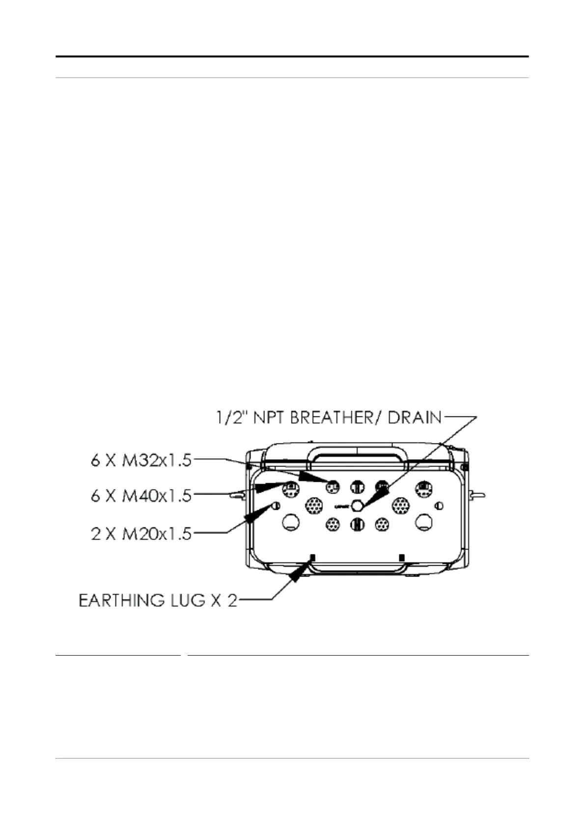
4.2.2 Metric Gland Entries
The MSC-L implements an optional metric gland assembly layout,
which supports the following glands.
2 x M20 (meters, solenoids)
6 x M40
6 x M32 (auxiliary)
1 x non-metric (½” NPT) not for wiring, but for optional breather.
FIGURE 4-2 Metric gland entries overview
 Loading...


