System Description - PCB Layout
Fusion4 MSC-L Part No.: 4418309_Rev09
3- 26 Installation & Operation Manual
Honeywell
3.6.1.1.2 Component Locations
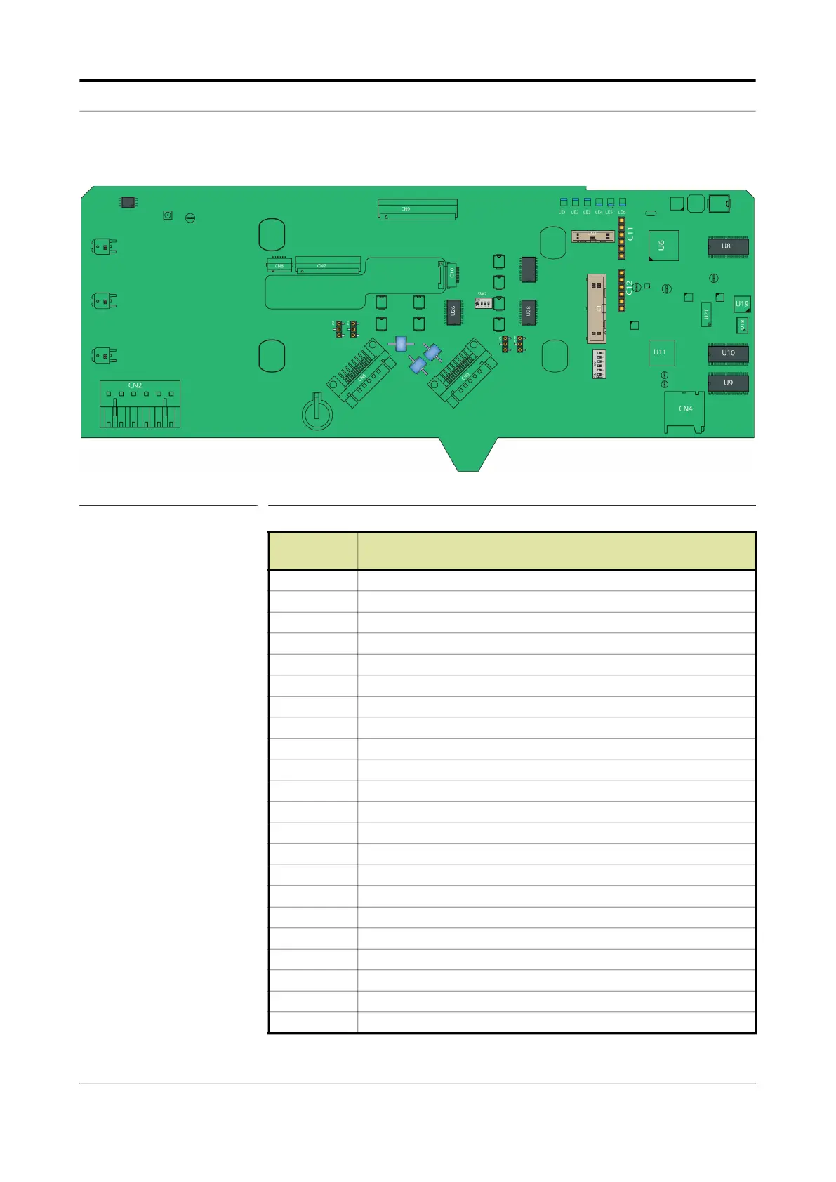
FIGURE 3-17 CAN-HMI-MSC component locations
Item
reference
Description
JP7, JP8 FlexConn jumpers for RS-485 CH5 finishing setting.
JP9 FlexConn jumpers for RS-485 CH3 finishing setting.
JP10 FlexConn jumpers for RS-485 CH4 finishing setting.
CN1 Programming connector for U11 (ARM controller).
CN2 LAD or keyboard connections to EX-IO-HMI-MSC-L.
CN3 Programming connector for U6 (FPGA).
CN4 microSD connector.
CN5, CN6 Connectors for interfacing with the ARM1-BACKPLANE-MSC.
CN7, CN8 Connectors for interfacing with the Varitronix display.
CN9, CN10 Connectors for interfacing with the Hitachi display.
LE1 Health of the board.
LE2 Configurable.
LE3 Configurable.
LE4 Ethernet auto negotiation.
LE5 Ethernet speed indicator.
LE6 FPGA Health.
U8,U9,U10 SDRAM.
U6 FPGA.
U11 ARM controller.
U19 Flash memory.
U1 A holder for IR receiver.
V2 Ambient light sensor.
 Loading...


