System Description - PCB Layout
Part No.: 4418309_Rev09 Fusion4 MSC-L
Honeywell Installation & Operation Manual 3 - 33
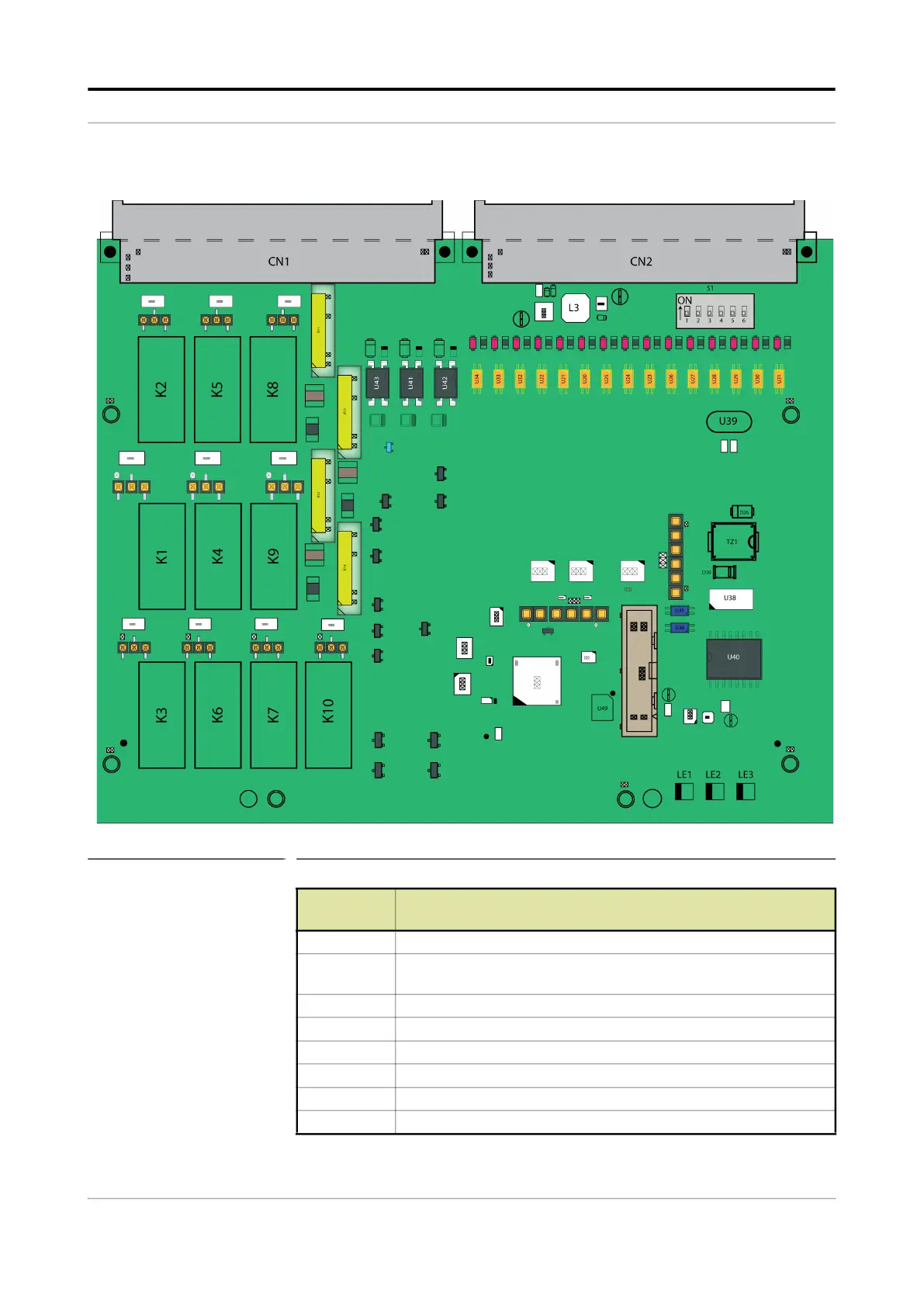
3.6.1.3.2 Component Locations
FIGURE 3-21 CAN-IN-OUT-MSC component locations
Item
reference
Description
JP7 to JP16 Jumper for EMR contacts setting.
CN1, CN2 Connectors for interfacing with the ARM1-BACKPLANE-MSC or the
ARM2-BACKPLANE-MSC.
LE1 Health of the board.
LE2 Configurable.
LE3 Configurable.
U44 Cortex M4 CPU.
K1-K10 Electro Mechanical Relay.
K11-K14 Solid State Relay.
 Loading...


