Installation - Wiring Termination Guidance
Fusion4 MSC-L Part No.: 4418309_Rev09
4 - 32 Installation & Operation Manual
Honeywell
4.7.3 General
CAUTION! IMPORTANT! All terminated cables must have
sufficient excess length to allow each PCB to be fully
withdrawn from the enclosure when the connectors
are still in place. This is performed to allow
connectors to be affixed to each board outside the
enclosure, before locating them inside, and to allow
each board to be fully withdrawn from the enclosure
before the connectors are removed. This negates the
requirement to attach and remove connectors inside
the enclosure and facilitates best practice for efficient
assembly and disassembly of the electronics stack.
4.7.3.1 Wire Sizes and Types
As there are no strictly prescribed wire sizes, the following guidelines
are recommended.
All I/O terminals accept wires with a cross section, an area of 0.2 to
2.5 mm
2
[AWG 24 to 14].
For mains/high voltage wiring, 1.5 mm
2
[AWG 16].
For low voltage wiring (DI, PO, AI, AO, RTD, and so on), 0.75 mm
2
[AWG 18] or 0.5 mm
2
[AWG 20].
The temperature rating of the field wiring must be at least 20 ºC [36
ºF] above the maximum operating temperature. Therefore, a rating of
85 °C [185 ºF] is suitable for the entire temperature range.
All primary wiring needs to be provided with insulation rated for
minimum 300 V, with a rated temperature of at least 105 °C [221 °F] and
with a conductor size of at least 0.75 mm
2
[AWG 18].
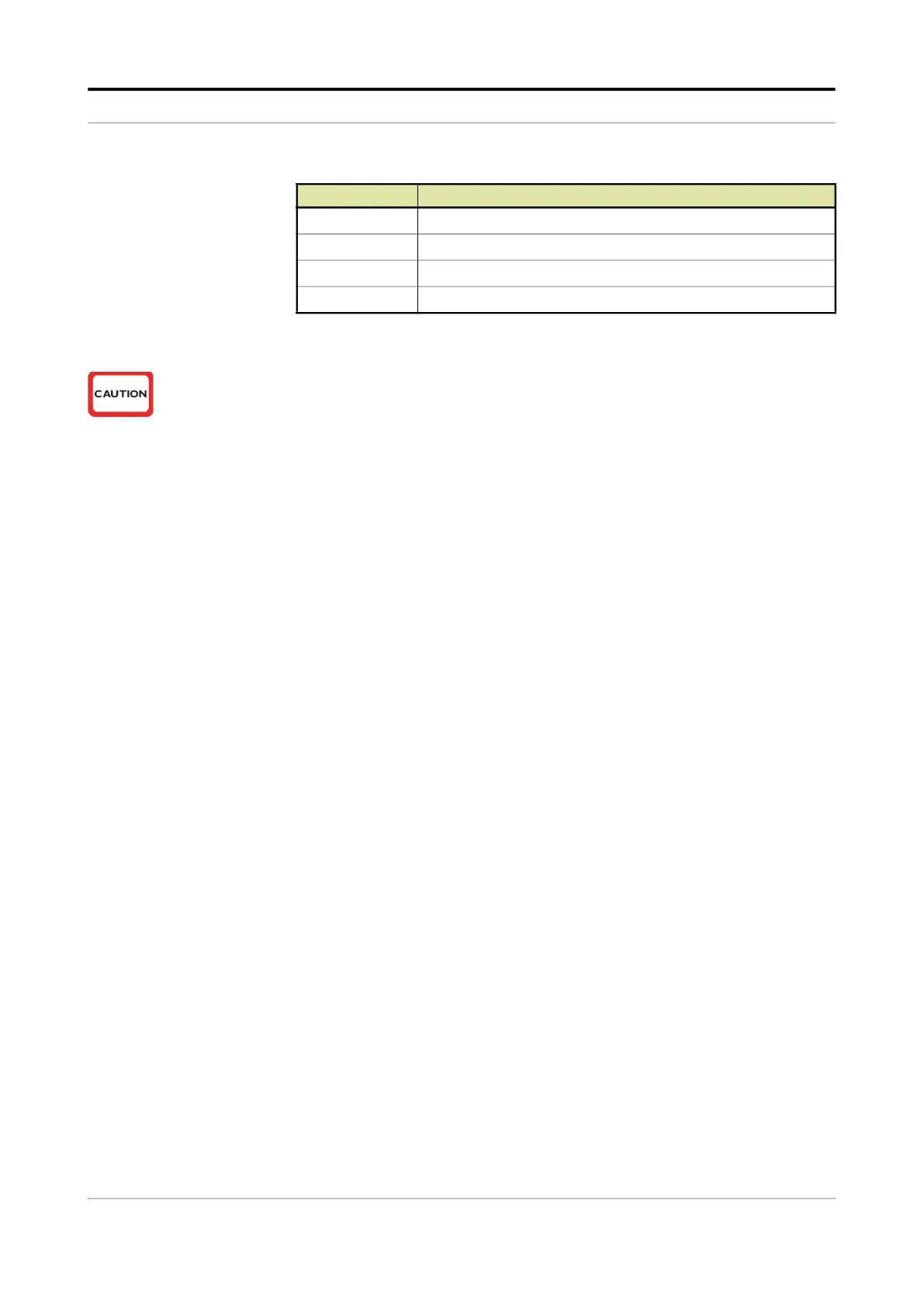
Yellow High voltage or Low voltage output signals
Green Low voltage signals
Black Communication signals
Blue Ex i signals
Color Function
 Loading...


