System Description - PCB Layout
Part No.: 4418309_Rev09 Fusion4 MSC-L
Honeywell Installation & Operation Manual 3 - 37
3.6.2.4 Fuse Boards
3.6.2.4.1 MSC-SHORTCUT-BOARD
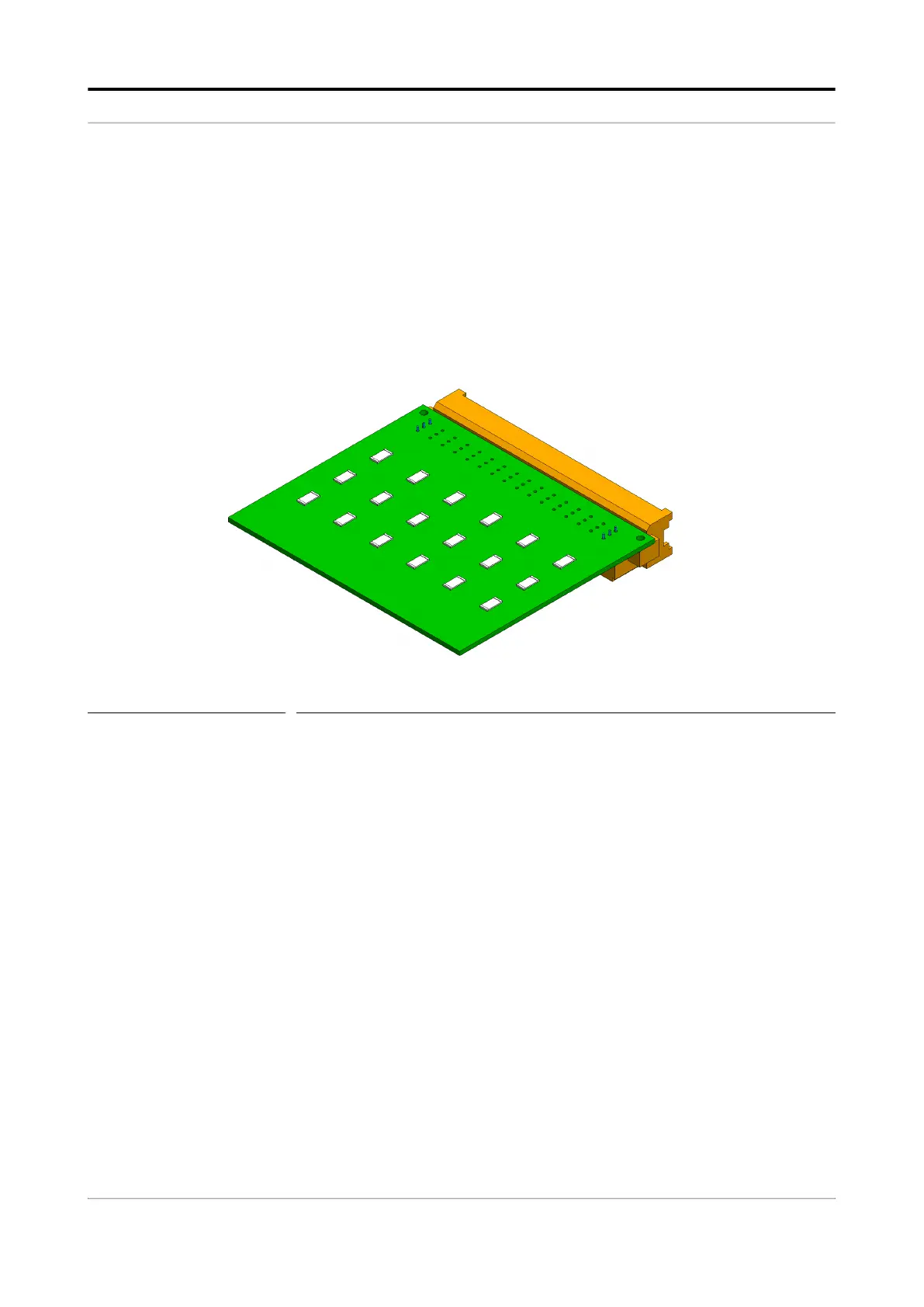
The MSC-SHORTCUT-Board is directly interfaced to the backplane of
the MSC-L through the 48 pin connector. The MSC-L contains the
Digital Output Solid State Relay AC (DO SSR AC) interface. The SSRs
are used for switching AC signals connected to the load. Every DO SSR
AC requires an optional fuse to protect the internal electronics so that
the high current can be withdrawn. Because the fuse is optional, 0 ohm
resistor can alternatively be connected in parallel to each fuse.
FIGURE 3-24 MSC-SHORTCUT-BOARD
3.6.3 Device Electrical Features
Following are the device electrical features of the MSC-L.
1. Internal power supply.
2. Seven microprocessor controlled modules.
3. Each I/O is galvanic isolated from the internal electronics for safety
performance.
4. Backplanes (ARM-1-BACKPLANE-MSC and ARM-2 BACKPLANE-
MSC) for external wiring.
5. Colored connectors on the backplane to distinguish different kinds of
signals.
3.6.4 System
Full-color (16 bits) WVGA, 8” diagonal display.
Multi-language support for main screens which are as follows:
• English US
• English UK
• French
 Loading...


