Operation - System Configuration
Part No.: 4418309_Rev09 Fusion4 MSC-L
Honeywell Installation & Operation Manual 5 - 117
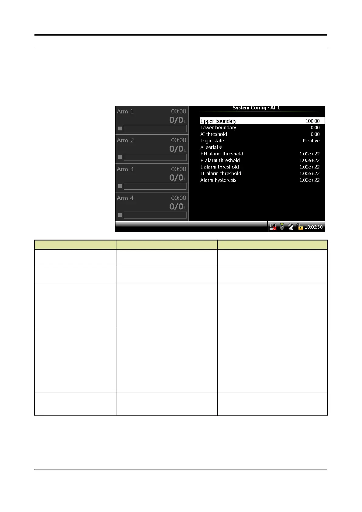
5.13.1.4.4 AI
On the System Config . I/O settings . AI screen, select the available
Analog Inputs (AIs). The following entities are displayed on the System
Config.AI-n screen.
Entity Description Value range
[PV value @20mA]
With this entity the process value at
20 mA can be configured.
default = 100.00
[PV value @4mA]
With this entity the process value at
4 mA can be configured.
default = 0.00
[AI threshold]
With this entity the analog input
threshold value defines the range for 0
or 1.
For example, 0 or not active from 4-12
mA and 1 or active from 12 mA to 20
mA.
default =
0.00
[AI logic state]
With this entity you can determine how
the injector controller uses the analog
input signal.
•
<Positive>: 0 or inactive from 4-[AI
threshold] mA and 1 or active from
[AI threshold] to 20 mA.
•
<Negative>: 1 or active from 4-[AI
threshold] mA and 0 or inactive from
[AI threshold] to 20 mA.
<Negative> (default)
<Positive>
[AI serial #]
With this entity you can enter the serial
number of the connected analog input
device or transmitter.
Alphanumeric string of maximum 8
characters.
 Loading...


