This ends the procedure.
Models 830/SB2 – Device Boards (DB1 and DB2)
1. Power off the system. (See “Powering On and Powering Off the System and
Logical Partitions” on page 922.)
2. Disconnect the power cord from the system unit.
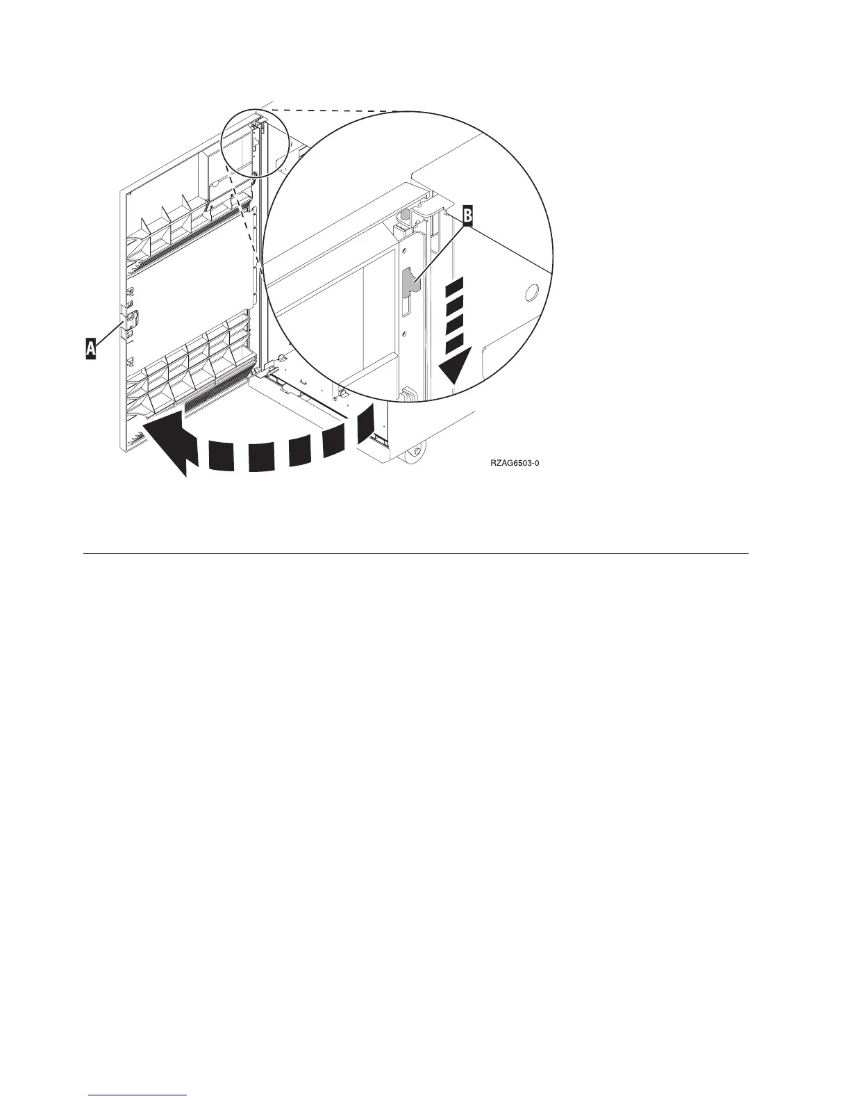
3. Open the front cover. (See “Models 830/SB2 with FC 9074 – Covers” on
page 663.)
Refer to “Models 830 and SB2 with FC 9074 – Final Assembly, Front” on page 812
and perform the following steps.
4. From the front of the system remove the following:
a. Remove the EMC access plates from the disk unit enclosures that are
located in front of the backplane that you are replacing. For location
information, see “Locations — Models 830, SB2 System Unit with FC 9074
Base I/O Tower” on page 709. Press the surfaces of the two latching
mechanisms together and tilt the top of the cover away from the frame to
remove it.
b. Record the locations of the disk units and then remove them from the disk
unit enclosures that you just uncovered.
Attention: The disk units are sensitive to electrostatic discharge (see
“Appendix C. Working with Electrostatic Discharge-Sensitive Parts” on
page 955).
c. Remove the screws that hold the disk unit cage assembly in to the frame.
d. Remove the two retaining screws that are located inside of the disk unit
cage assembly (the top right and bottom left corners).
e. Remove the disk unit cage assemblies.
Figure 19. Front Cover - Removal
Remove and Replace Procedures
664
iSeries Model 830, 840, SB2, and SB3 Problem Analysis, Repair and Parts V5R1
 Loading...


