11. Place one of the new Battery Warning label (PN 04K9421) over the 2 new
batteries in Battery positions1&2which were just installed. Place the other
new Battery Warning label over the 2 new batteries in Battery positions3&4
which were just installed.
12. Reinstall the card.
This ends the procedure.
Type 4758 – Disablement Procedure
Attention: For security reasons, when replacing the cryptographic coprocessor,
use the following procedure.
This procedure demonstrates the proper method for disabling the Type 4758 PCI
Cryptographic Coprocessor card. The disablement procedure assures that the
contents of the Coprocessor’s protected memory are set to zeroes. The
cryptographic master key and other data stored in the protected memory will be
lost.
CAUTION:
The battery is a lithium battery. To avoid possible explosion, do not burn or
charge the battery. Exchange only with the IBM-approved part. Discard the
battery as instructed by local regulations. (RSFTC227)
1. Remove the 4758 PCI Cryptographic Coprocessor card from the system (see
“Models 830/SB2 with FC 9074 – Cards – Concurrent” on page 655, “Models
840/SB3, FC 8079 (lower half), FC 9079 Cards — Concurrent” on page 678, “FC
5074, FC 5079 – Cards – Concurrent” on page 620, or “FC 5075 – Cards –
Concurrent” on page 638).
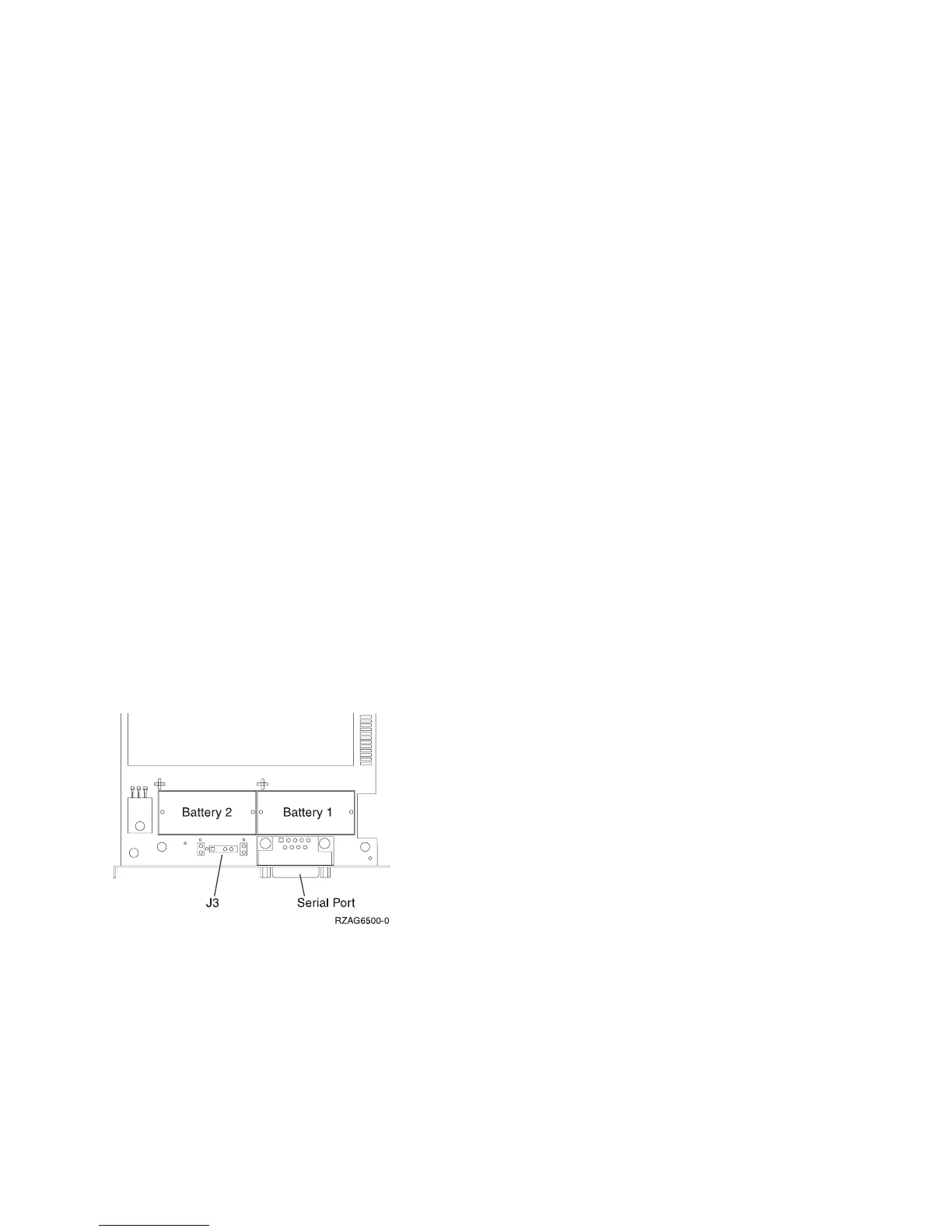
2. Find the location of the four lithium batteries. They are located in adjacent
holders, with the Battery 2 above the J3 connector. Refer to the illustration
below.
Note: The 4758-023 card contains 4 batteries, even though only 2 batteries are
shown in the figure above. Battery 3 is next to Battery 1, and Battery 4 is
next to Battery 2.
Note: The loss of battery power erases data stored in the card’s protected
memory and renders the card useless.
3. Remove the battery in the ″Battery1″ holder (lower right side).
4. Remove the battery in the ″Battery2″ holder (lower left side).
Figure 25. Battery Locations on the 4758 PCI Cryptographic Coprocessor
Remove and Replace Procedures
Chapter 4. Removal and Installation Procedures 689
 Loading...


