January 2007 183
Intel
®
855GME Chipset and Intel
®
6300ESB ICH Embedded Platform Design Guide
Hub Interface
Hub Interface 8
The GMCH and 6300ESB ballout assignments have been optimized to simplify the Hub Interface
routing between these devices. It is recommended that the Hub Interface signals be routed directly
from the GMCH to the 6300ESB with all signals referenced to V
SS
. Layer transition should be
keep to a minimum. When a layer change is required, use only two vias per net and keep all data
signals and associated strobe signal on the same layer.
The Hub Interface signals are broken into two groups: data signals (HI) and strobe signals
(HI_STB). For the 8-bit Hub Interface, HI[11:0] are associated with HI_STB/HI_STBS and
HI_STB#/HI_STBF.
Note: These routing guidelines are created using the stack-up described in Figure 2, “Recommended
Board Stack-up Dimensions” on page 34.
8.1 8-Bit Hub Interface Routing Guidelines.
8.1.1 8-Bit Hub Interface Data Signals
The 8-bit Hub Interface data signal traces (HI[11:0]) should be routed through stripline or
microstrip routing with 5 mil width and 15 mil spacing. (See Table 66.) These signals may be
routed 5 mil width and 5 mil spacing for navigation around components, mounting holes or in order
to break out of the GMCH and the 6300ESB package. The signals must be separated no longer than
300 mils from the package.
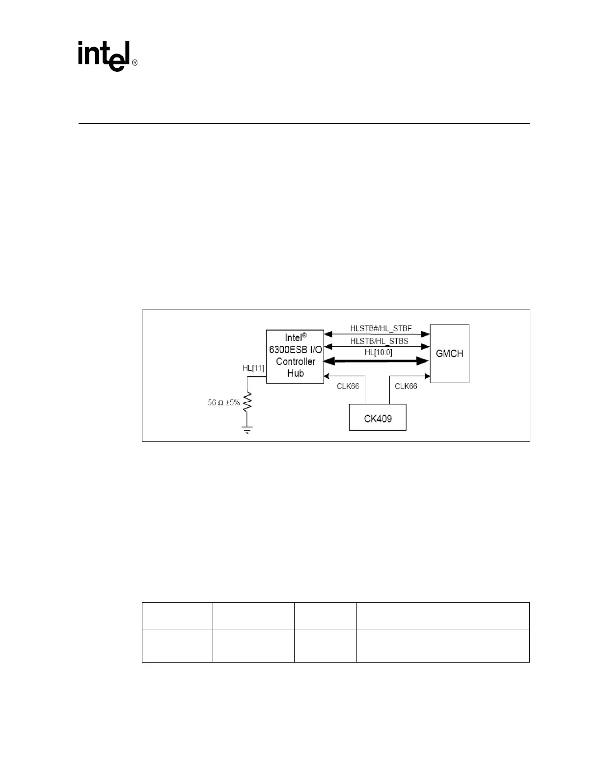
Figure 85. 8-Bit Hub Interface Routing Example
Table 66. Hub Interface 1.5 Data Signals Routing Summary
Digital Signal
Requirement
Maximum Trace
Length
Referencing Data Signal Length Matching
5 mil width, 15 mil
spacing
8 inches Ground
Each strobe signal must be the same length,
and each data signal must be matched within
± 0.25 inches of the strobe signals.