January 2007 39
Intel
®
855GME Chipset and Intel
®
6300ESB ICH Embedded Platform Design Guide
Intel
®
Pentium
®
M/Celeron
®
M Processor FSB Design and Power Delivery Guidelines
relationship given below does not take into account the normal tolerances that are allowed for in
the recommended board stack-up’s parameters. For the recommended stack-up shown in Figure 2,
the calculated capacitive coupling maximum value is represented by the following relationship:
(C
MUTUAL
/C
SELF
) x 100 = 8.15%
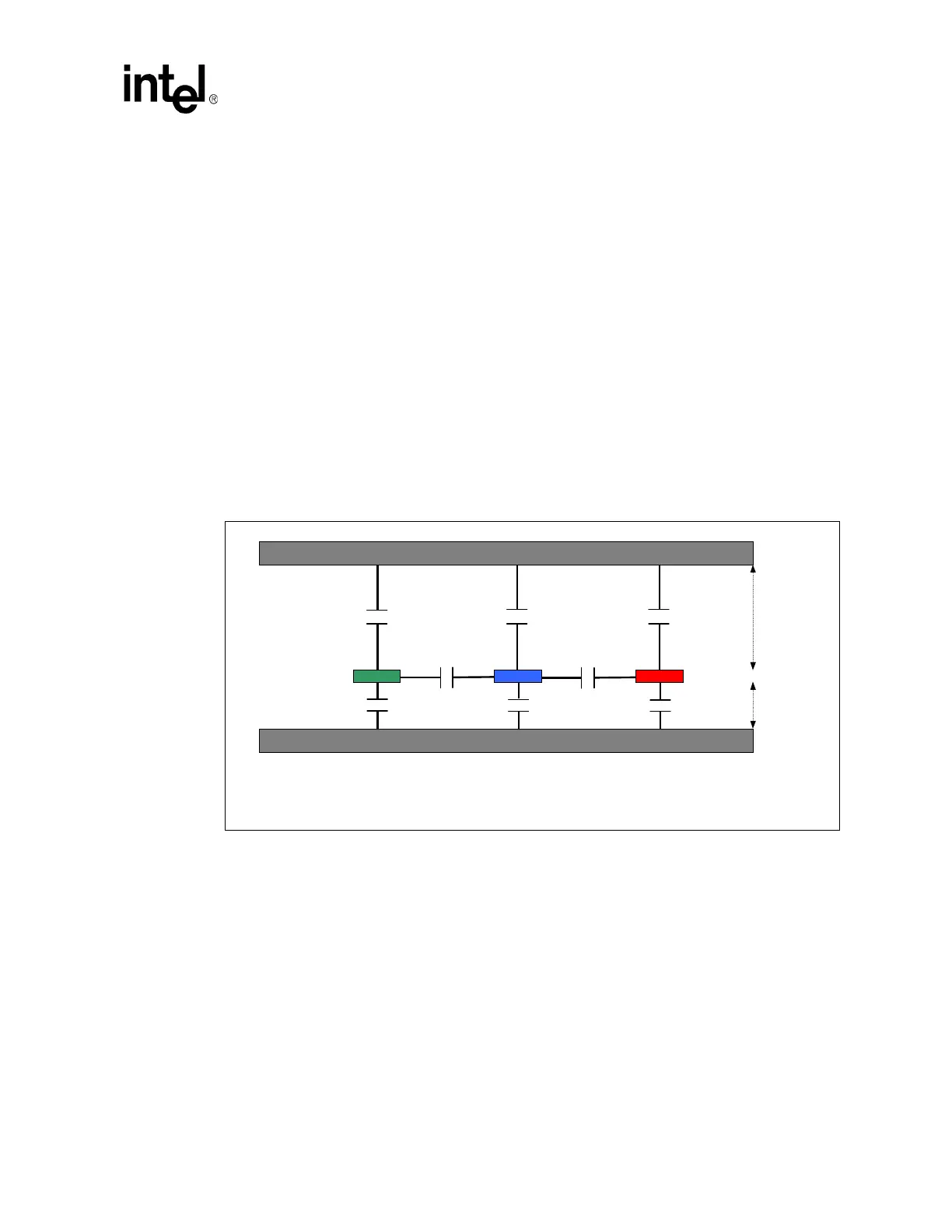
As shown in Figure 6, the coupling values are calculated based on a three-line model, represented
by Trace 1, Trace 2, and Trace 3. Based on the capacitive coupling model shown, the
aforementioned parameters are:
C
MUTUAL
= C21 + C23
C
SELF
= C22 (Trace 2, i.e., CS2a + CS2b)
When a stack-up that is employed does not adhere to the recommended stack-up, a new extraction
must be made for the stack-up using a 2D field solver program. According to the 2D field solver
results, new coupling calculations must be performed to ensure that the coupling results are less
than the aforementioned capacitive coupling maximum value of 8.15 percent. When the coupling
results are greater than the maximum value, additional system-level simulations must be performed
to avoid any signal quality issues due to crosstalk effects.
4.1.1.4 Signal Propagation Time-to-Distance Relationship and Assumptions
Due to the high-frequency nature of some interfaces and signals, length matching may or may not
exist as part of the routing requirements for a given interface. In general, the tolerances that
specific signals in a bus must be routed to are stated as a length measured in mils or inches and are
specific to the recommended motherboard stack-up (refer to Section 3.1). However, some length
matching tolerances for signals listed in this design guide may be stated as a measurement of time.
In such cases, the correlation of the period of time to an actual length value depends on board
stack-up.
Based on the recommended stack-up, the signal propagation time to distance relationship, for the
purpose of this design guide, is as follows:
• Strip-line (internal layer) routing: 180 ps for 1.0 inch
Figure 6. Recommended Stack-up Capacitive Coupling Model
Trace 1 Trace 2
Trace 3
GND
GND
C21
C23
4.8 M
11.2 M
CS2b
CS2aCS1a
CS3a
CS1b
CS3b
Note: CS1a + CS1b = C11
CS2a + CS2b = C22
CS3a +CS3b = C33
 Loading...


