January 2007 189
Intel
®
855GME Chipset and Intel
®
6300ESB ICH Embedded Platform Design Guide
Hub Interface
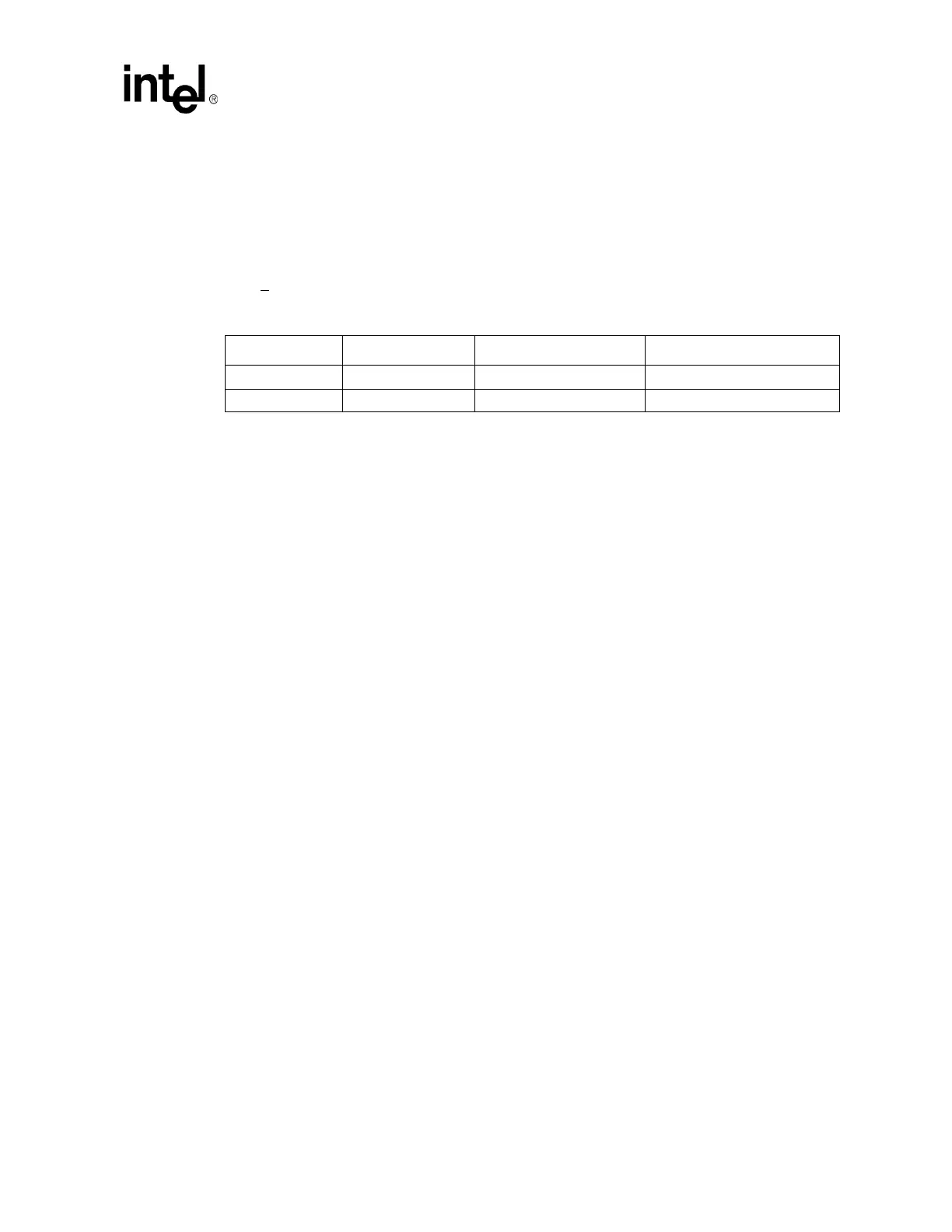
8.1.5 Hub Interface Compensation
This section documents the routing guidelines for the 8-bit Hub Interface using enhanced (parallel)
termination (the method of termination is dependant upon the Northbridge). This Hub Interface
connects the Intel
®
855GME chipset Graphics Memory Controller Hub (82855GME) to the
6300ESB. As shown in Table 71, the 6300ESB shall strap its HLRCOMP pin to V
CC
HI = 1.5 V
and the GMCH shall strap its HLRCOMP pin to V
CC
HL =1.35 V. The trace impedance must equal
55
Ω + 15 percent.
8.1.6 8-Bit Hub Interface Decoupling Guidelines
To improve I/O power delivery, use two 0.1 µF capacitors per each component (i.e., the 6300ESB
and GMCH). These capacitors should be placed within 50 mils from each package, adjacent to the
rows that contain the Hub Interface. When the layout allows, wide metal fingers running on the
V
SS
side of the board should connect the V
CC
HI=1.5 V side of the capacitors to the V
CC
HI=1.5 V
power pins. Similarly, when the layout allows, metal fingers running on the V
CC
HI=1.5 V side of
the board should connect the ground side of the capacitors to the V
SS
power pins.
8.1.7 Terminating HI_11 If Not Used
The HL[11] signal exists on the 6300ESB but not the GMCH and is not used on the platform.
HL[11] must be pulled down to ground via a 56
Ω resistor.
Table 71. Hub Interface RCOMP Resistor Values
Component Trace Impedance HLRCOMP Resistor Value HLRCOMP Resistor Tied to
6300ESB 55
Ω ± 15% 48.1 Ω ± 1% Vcc1_5
GMCH 55
Ω ± 15% 37.4 Ω ± 1% Vcc1_35
 Loading...


