January 2007 291
Intel
®
855GME Chipset and Intel
®
6300ESB ICH Embedded Platform Design Guide
Schematic Checklist Summary
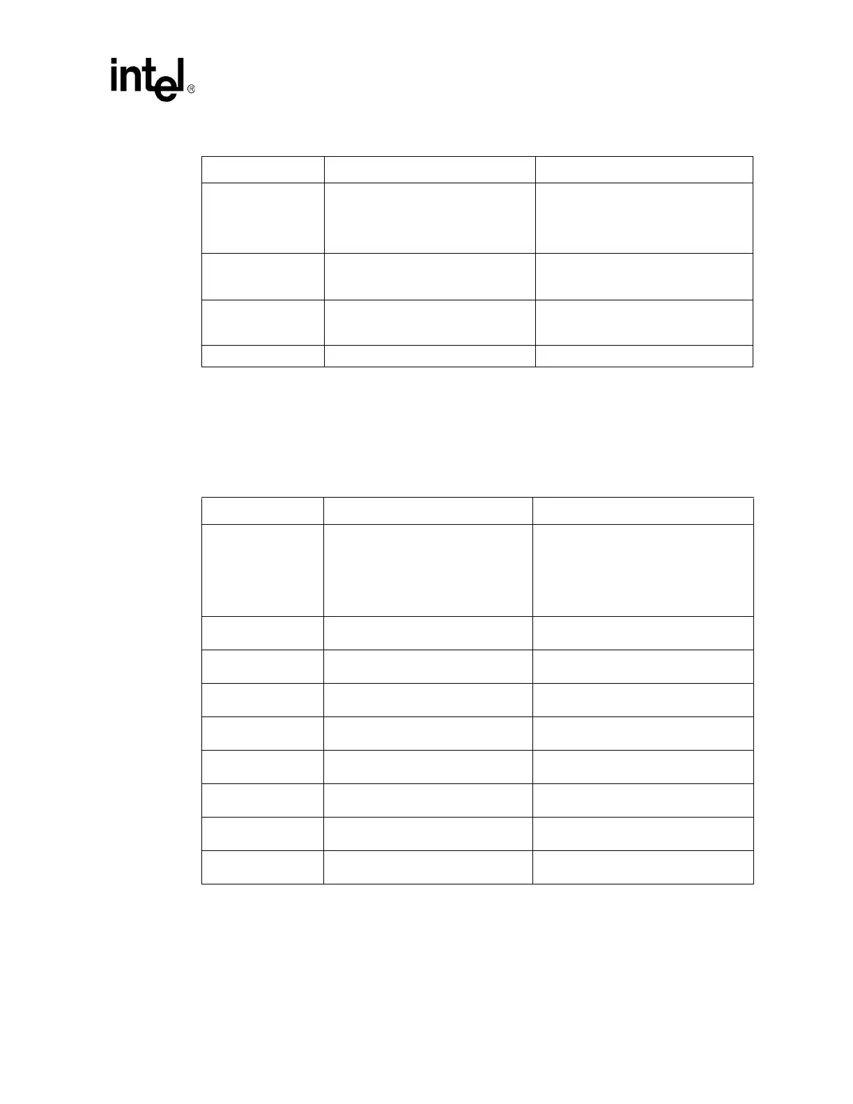
12.4.8 CPU Signals Checklist
Note: Ensure processor recommendations for the following signals are taken into consideration as well as
the following recommendations.
SYS_RESET#
Recommend an 8.2 K
Ω pull-up resistor
to V
CCSus
3.3. Also recommend a
100
Ω to 1 KΩ pull-down resistor
isolated from SYS_RESET# by means
of a normally open switch.
Input to 6300ESB cannot float. This pin
forces an internal reset to the 6300ESB
after the signal is internally debounced.
THRM#
Connect to temperature sensor. Pull-up
when not used (an 8.2 K
Ω pull-up
resistor to V
CC
3.3).
Input to 6300ESB cannot float. THRM#
polarity bit defaults THRM# to active low,
so pull up.
THRMTRIP#
A pull-up resistor to the V_CPU_IO well
(62
Ω). See Processor Design Guide to
insure proper pull-up value.
Input to the 6300ESB cannot float.
VRMPWRGD A 8.2 K
Ω pull-up to Vcc3.3
Table 139. CPU Signals Checklist
Checklist Items Recommendations Reason/Impact
A20GATE
Pull-up signal to V
CC
3.3 through a
10 K
Ω resistor.
or
If software control of A20M# is desired,
connect to a GPIO that is driven high at
the rising edge of reset
Typically driven by an open drain external
micro-controller.
If this signal is not used pull-up to V
CC
3.3
through a 10 K
Ω resistor.
A20M#, CPUSLP# No external resistors required
Push/pull buffers now drive the output
signals.
FERR#
Requires a external pull-up resistor to
V_CPU_IO.(62
Ω)
IGNNE# No external resistors required
Push/pull buffers now drive the output
signals.
INIT#
See Section 9.13.4 for more infor-
mation.
INTR, NMI No external resistors required
Push/pull buffers now drive the output
signals.
RCIN#
Pull-up signals to V
CC
3.3 through a
10 K
Ω resistor.
Typically driven by an open drain external
micro-controller.
SERIRQ
External 8.2 K
Ω pull-up resistor to
V
CC
3.3 is recommended.
SMI#, STPCLK# No external resistors required
Push/pull buffers now drive the output
signals.
Table 138. Power Management Checklist (Sheet 2 of 2)
Checklist Items Recommendations Reason/Impact
 Loading...


