January 2007 231
Intel
®
855GME Chipset and Intel
®
6300ESB ICH Embedded Platform Design Guide
Intel
®
6300ESB Design Guidelines
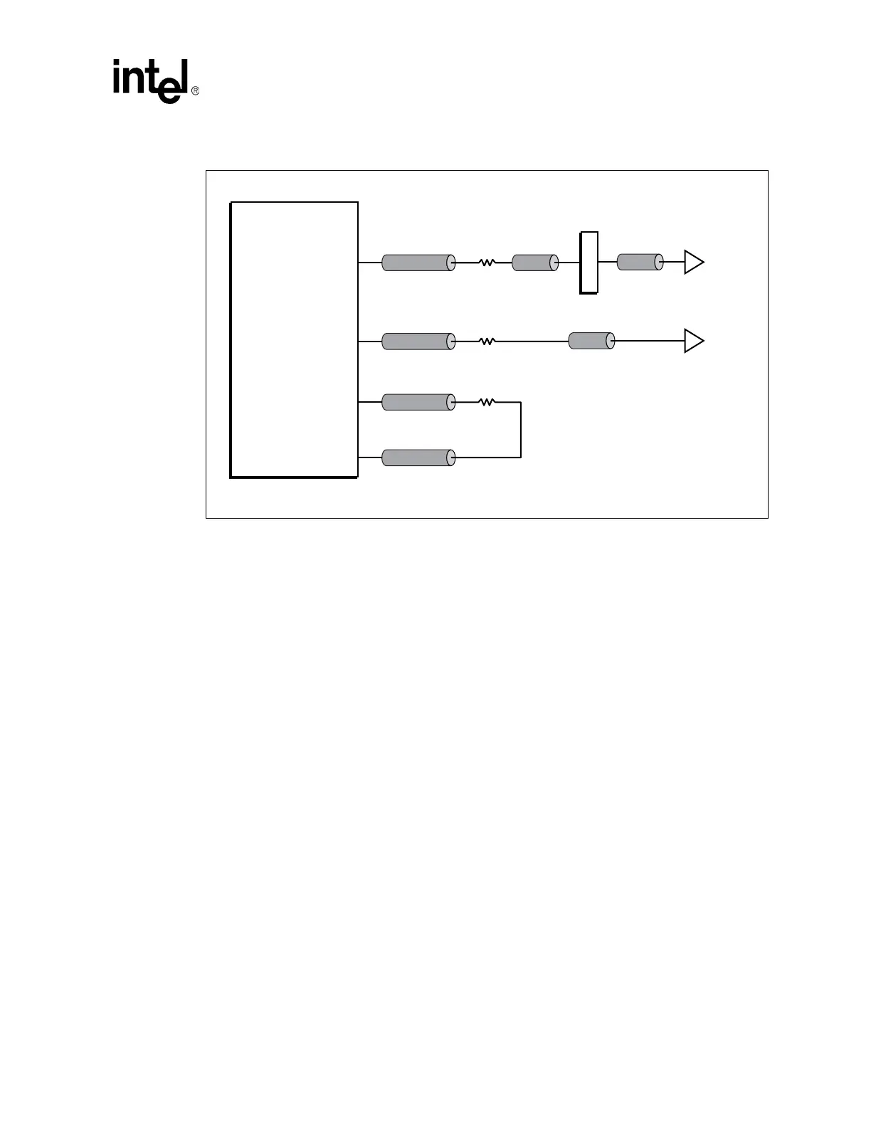
9.10.1.1 PCI-X Clock Length Matching Guidelines
The total path length of each clock signal must be matched to all of the other clock lines to ensure
that all of the clock edges arrive at the clock inputs of the devices at the same time. Figure 125
above diagrams the general clock layout and the following formulas give the clock matching
requirements.
Note: Maximum path length of any clock should be kept below 30 inches.
These guidelines account for the fact that there is some delay though the PCI-X mated connector,
and through the 2.5 inches of specified trace length for the daughter cards. The PXPCLKI signal is
a clock that is fed back to the 6300ESB chip as a timing reference and must be matched to the other
clocks.
• The length of the sum of (TL1 + TL2) must be matched to within ± 0.1 inch between all clocks
passing to PCI-X connectors.
• For down devices and the PXPCLKI feedback clock: TL1 + TL3 = TL1 + TL2 (for slots) + 3.2
inches
± 0.1 inch (the extra 3.2 inches account for the extra delay through the connector and
traces of daughter cards).
9.10.2 IDSEL Series Resistor
The value for the series resistor on the IDSEL signal should be 100 Ω. No device is permitted to
connect IDSEL to PXAD[16] (device number 0), since this device number is reserved for the
source bridge. For systems that have add-in board connectors and connect IDSEL to the PXAD
bus, the first two add-in board connectors are recommended to be connected according to
Table 100 to minimize the length of the IDSEL trace.
Figure 125. 66 MHz Clock Signal Configuration
B2901-01
TL1
TL3
R1
TL3
TL1
R1
2.5"
Card
Clock
Input
Down
Clock
Input
TL2
TL1
PXPCLKO[0:3]
PXPCLKO[0:3]
PXPCLKI
PXPCLKO4
R1
CONN
0.7"
Intel
®
6300ESB
I/O Controller Hub
 Loading...


