38
Intel
®
855GME Chipset and Intel
®
6300ESB ICH Embedded Platform Design Guide
Intel
®
Pentium
®
M/Celeron
®
M Processor FSB Design and Power Delivery Guidelines
effects of crosstalk are difficult to simulate. The timing and layout guidelines for the Intel Pentium
M/Celeron M Processor have been created with the assumption of a 2:1 trace spacing to reference
plane ratio. A smaller ratio has an unpredictable impact due to crosstalk.
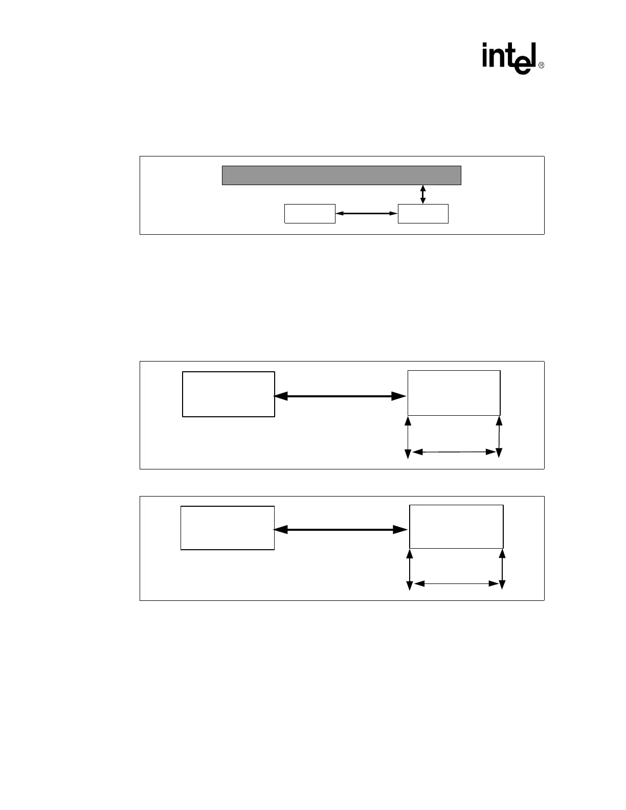
4.1.1.2 Trace Space to Trace Width Ratio
Figure 3 illustrates the recommended relationship between the edge-to-edge trace spacing versus
trace width ratio for the best signal quality results. In general, a 3:1 trace space-to-trace width ratio
(shown in Figure 5) is preferred and highly recommended. In case of routing difficulties on the
motherboard, using a 2:1 ratio (shown in Figure 4) would be acceptable only if additional
simulations conclude that it is possible, which may include some changes to the stack-up or routing
assumptions.
4.1.1.3 Recommended Stack-up Calculated Coupling Model
The importance of maintaining an adequate trace space to trace width ratio is to achieve the best
signal quality possible given routing constraints. The simulations performed that resulted in the
recommended 3:1 trace spacing to trace width ratio are to keep the coupling between adjacent
traces below a maximum value. For the recommended stack-up, the constants shown in Figure 2
are assumed to be constant for a typical stack-up. This means the mutual to self-coupling
Figure 3. Trace Spacing versus Trace to Reference Plane Example
Reference Plane (VSS)
Trace
Trace
X
2X
Figure 4. Two-to-One Trace Spacing-to-Trace Width Example
Figure 5. Three-to-One Trace Spacing-to-Trace Width Example
Trace
Trace
2X
X
Trace
Trace
3X
X
 Loading...


