294
Intel
®
855GME Chipset and Intel
®
6300ESB ICH Embedded Platform Design Guide
Schematic Checklist Summary
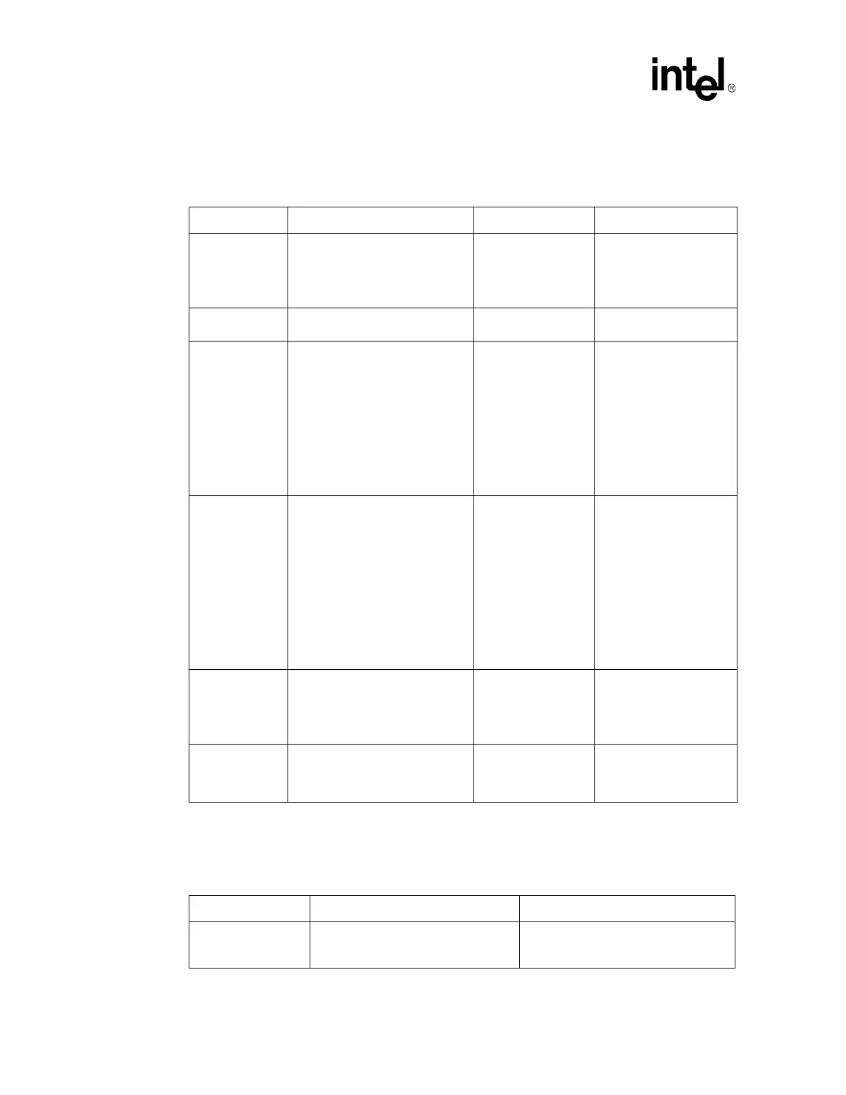
12.4.12 AC’97 Checklist
12.4.13 Miscellaneous Signals
Table 143. AC’97 Checklist
Checklist Items Recommendations Interface Not Used Reason/Impact
AC_BITCLK
No extra pull-down resistors
required.
Series termination resistor 33
Ω to
47
Ω from the motherboard codec
to the 6300ESB.
May leave as no
connect
This pin has a weak
internal 20 K
Ω nominal
pull-down.
AC_RST#
No extra pull-down resistor
required.
May leave as no
connect
Internal Pull-down
(9 K
Ω -50 KΩ)
AC_SDOUT
Use a jumper to an 8.2 K
Ω pull-up
resistor. Should not be stuffed for
default operation.
Series termination resistor 0
Ω to 47
Ω to the on-board codec and to the
CNR.
May leave as no
connect
This pin has a weak
internal 20 K
Ω nominal
pull-down.
Strap Function: Safe Mode
(See the 6300ESB EDS
for more information)
To properly detect a safe-
mode condition, a strong
pull-up will be required to
override this internal
pull-down.
AC_SDIN[2]
Requires a 10 K
Ω pull-down to
GND when a CNR card is used on
the platform.
Series termination resistors 33
Ω to
47
Ω from the AC_SDIN lines to the
6300ESB.
May leave as no
connect
This pin has a weak
internal 20 K
Ω nominal
pull-down. For platforms
routing AC_SDIN[2] to
CNR, the additional
10 K
Ω pull-down is
required to set the proper
DC level for CNR card
switching circuitry.
Used for a codec
detection/addressing
mechanism on the CNR
card.
AC_SDIN[1],
AC_SDIN[0]
Internal pull-downs in the 6300ESB;
no external pull-downs required.
Series termination resistors 0
Ω to
47
Ω from the AC_SDIN lines to the
6300ESB.
May leave as no
connect
These pins have a weak
internal 20 K
Ω nominal
pull-down.
AC_SYNC
No extra pull-down resistor
required.
May leave as no
connect
Some implementations
add termination for signal
integrity. This signal is
platform specific.
Table 144. Miscellaneous Signals Checklist
Checklist Items Recommendations Reason/Impact
CLK14
Ensure this pin is connected to a 14
MHz clock output of the clock generator
(CK409) through a 33
Ω resistor
 Loading...


