228
Intel
®
855GME Chipset and Intel
®
6300ESB ICH Embedded Platform Design Guide
Intel
®
6300ESB Design Guidelines
9.10 PCI-X Design Guidelines
This section contains guidelines for connecting and routing the 6300ESB PCI-X interface. The
6300ESB supports up to four PCI-X devices. This section provides guidelines for PCI-X connector
and motherboard design, including component and resistor placement. When considering PCI-X
device configurations refer to Table 94 which shows all the slot/device-down options possible with
the 6300ESB PCI-X Interface.
Note: Bounded by six electrical loads and four REQ/GNT pairs (1 slot = 2 electrical loads)
Note: These routing guidelines are created using the stack-up described in Section 3.1, “Nominal Board
Stack-Up” on page 33.
The PCI-X interface may be routed with 5 mils traces on 12 mils spaces (dependent upon stackup
parameters), and must be less than eight inches long (from 6300ESB to PCI-X connector). Trace
spacing of 5 mils is only acceptable when necessary to route through pin fields. For more
information, refer to the
PCI-X Specification, Rev 1.0.
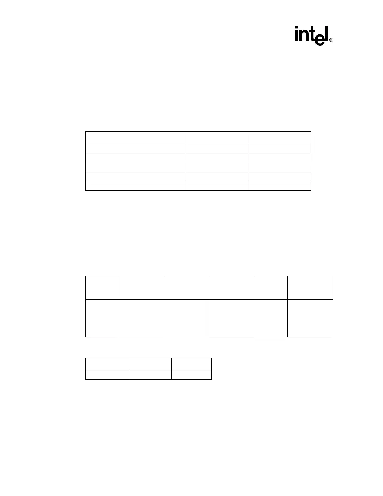
Table 94. PCI-X Slot/Device Configurations
PCI-X 1.0 Segment Configurations # of Slots # of Devices Down
6 loads, 3 pairs REQ/GNT 3 0
5 loads, 3 pairs REQ/GNT 2 1
6 loads, 4 pairs REQ/GNT 2 2
5 loads, 4 pairs REQ/GNT 1 3
4 loads, 4 pairs REQ/GNT 0 4
Table 95. PCI-X Routing Summary
Trace
Impedance
PCI-X Routing
Requirements
Maximum Trace
Length (To first
connector)
Maximum Trace
Length Between
Connectors
Clock
Signal
Spacing
PCI-X Signal
Length Matching
55
Ω ± 10%
5 mils width, 12
mils spacing
(based on
stackup
assumptions in
Section 3.1)
8 inches 1.5 inches 50 mils
Clocks coming
from the clock
driver must be
length matched.
Table 96. PCI-X Frequencies
Frequency Max Slots Voltage
66 MHz 3 3.3 V
 Loading...


