January 2007 269
Intel
®
855GME Chipset and Intel
®
6300ESB ICH Embedded Platform Design Guide
Schematic Checklist Summary
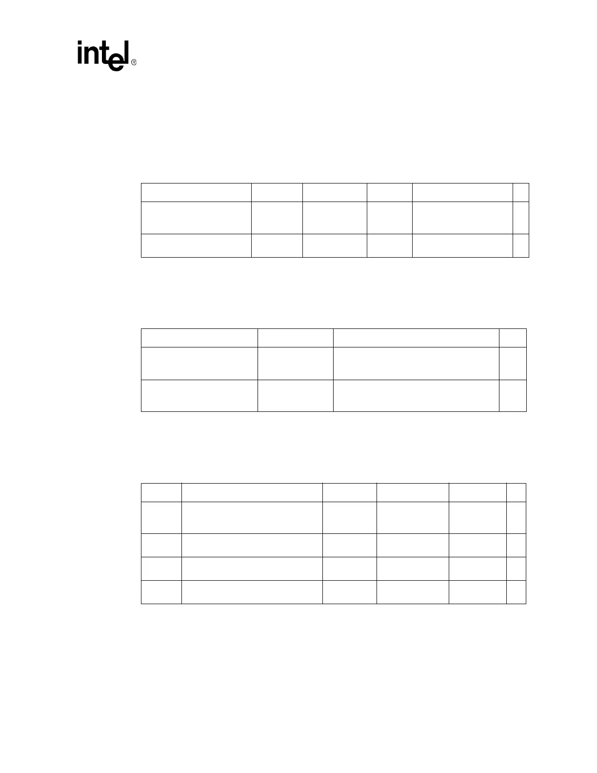
12.1.3 Decoupling Recommendations
12.1.3.1 VCCP (I/O)
Table 117 presents the VCCP (I/O) decoupling recommendations.
12.1.3.2 VCCA (PLL)
Table 118 presents the VCCA (PLL) decoupling recommendations.
12.1.3.3 VCC (CORE)
Table 119 presents the VCC (CORE) decoupling recommendations.
Table 117. VCCP (I/O) Decoupling Recommendations
Description C, μF ESR, mΩ ESL, nH Notes
√
Low Frequency Decoupling
(Polymer Covered Tantalum -
POSCAP, Neocap, KO Cap)
2 x 150
μF42mΩ (typ)/2 2.5 nH/2
Refer to Section 4.4.4 for
implementation of
recommended decoupling.
High Frequency Decoupling
(0603 MLCC, >= X7R)
10 x 0.1
μF16mΩ (typ)/10 0.6 nH/10
Table 118. VCCA (PLL) Decoupling Recommendations
Description C, μF Notes
√
Mid Frequency Decoupling
(Polymer Covered Tantalum -
POSCAP, Neocap, KO Cap)
4 x 10
μF
Place one 10
μF and one 0.01 μF for each
VCCA pin.
High Frequency Decoupling
(0603 MLCC, >= X7R). Place
next to Pentium M processor.
4 x 0.01
μF
Place one 10
μF and one 0.01 μF for each
VCCA pin.
Table 119. VCC (CORE) Decoupling Recommendations (Sheet 1 of 2)
Option Description C, μF ESR, mΩ ESL, nH √
#1
Low-Frequency Decoupling (Polymer
Covered Tantalum – POSCAP,
Neocap, KO Cap)
12 x 150 μF36mΩ (typ)/12 2.5 nH/12
Mid-Frequency Decoupling
(0612 MLCC, X5R or better)
15 x 2.2
μF5mΩ (typ)/15 0.2 nH/15
#2
Low-Frequency Decoupling
(1206 MLCC, X5R or better)
40x10
μF5mΩ (typ)/40 1.2 nH/40
Mid-Frequency Decoupling
(0612 MLCC, X5R or better)
15 x 2.2
μF5mΩ (typ)/15 0.2 nH/15
NOTES:
1. Decoupling guidelines are recommendations based on Intel reference board design. The Intel Customer
Reference Board uses option #4. This is the preferred recommendation for decoupling.
2. When deciding on overall decoupling solution, customers may need to take layout and PCB board design
into consideration.
3. Option #4 is to be used with small footprint (100 mm
2
or less) 0.36 µH ± 20% inductors.