290
Intel
®
855GME Chipset and Intel
®
6300ESB ICH Embedded Platform Design Guide
Schematic Checklist Summary
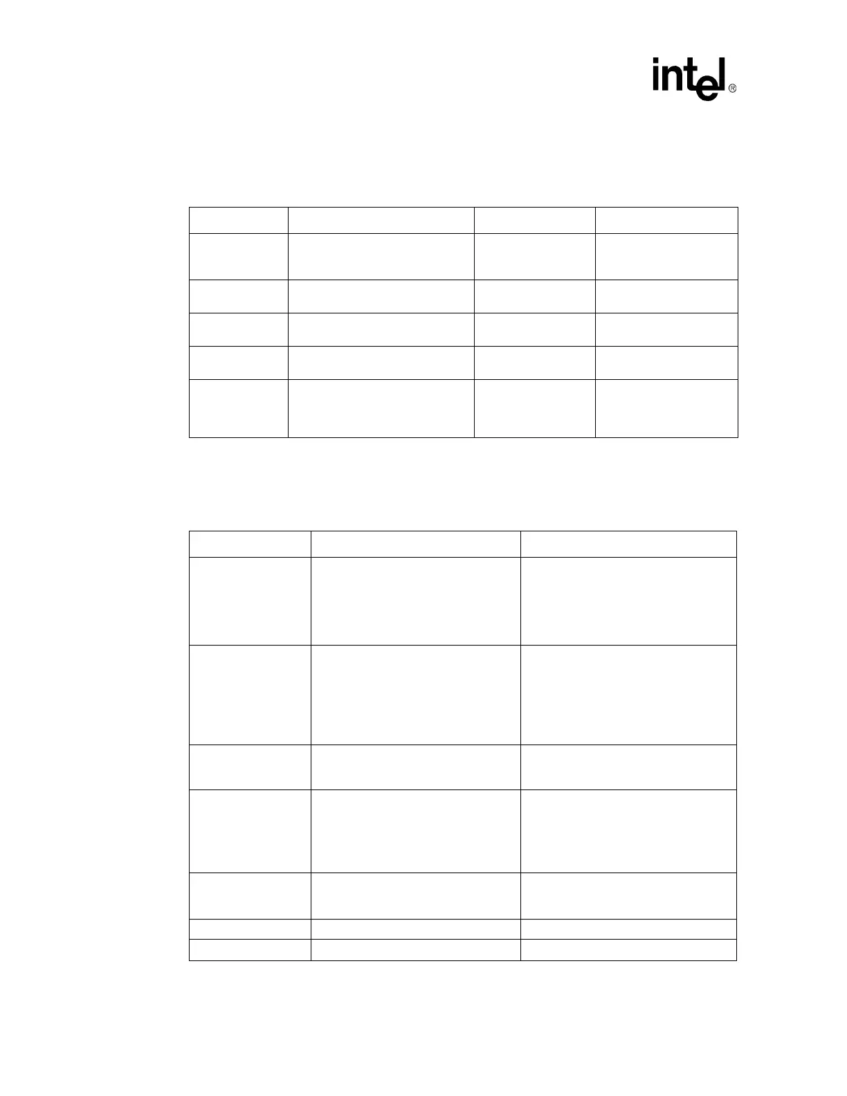
12.4.6 USB Checklist
12.4.7 Power Management Checklist
Table 137. USB Checklist
Checklist Items Recommendations Interface Not Used Reason/Impact
USBP[0:3]P,
USBP[0:3]N
No external resistors are required.
May leave as no
connect
Effective output driver
impedance of 45
Ω
provided.
OC[0:3]# No external resistors are required.
May leave as no
connect
USBRBIAS#
Connected to the same 22.6
Ω ±1%
resistor to GND as USBRBIAS.
May leave as no
connect
USBRBIAS 22.6
Ω ±1% connected to GND.
May leave as no
connect
CLK48
Ensure this pin is connected to a
48MHz clock output of the clock
generator (CK409) through a 33
Ω
resistor
May leave as no
connect
Table 138. Power Management Checklist (Sheet 1 of 2)
Checklist Items Recommendations Reason/Impact
PWROK
Recommend a 10 K
Ω pull-down to GND.
This signal should be connected to
power monitoring logic, and should go
high no sooner than 100 ms after both
V
CC
3.3 and V
CC
1_5 have reached their
nominal voltages.
Timing Requirement
RSMRST#
Recommend a 10 K
Ω pull-down resistor
to GND.
This signal should be connected to
power monitoring logic, and should go
high no sooner than 10 ms after both
V
CC
Sus3.3 and V
CC
Sus1_5 have
reached their nominal voltages.
Timing Requirement
PWRBTN# No extra pull-up resistors
This signal has an integrated pull-up of
18 K
Ω - 42 KΩ. This signal is internally
debounced inside the 6300ESB.
RI#
RI# does not have an internal pull-up.
Recommend an 8.2 K
Ω pull-up resistor
to V
CC
Sus3.3
When this signal is enabled as a wake
event, it is important to keep this signal
powered during the power loss event. If
this signal goes low (active), when power
returns the RI_STS bit will be set and the
system will interpret that as a wake event.
SLP_S3#,
SLP_S4#,
SLP_S5#
No pull up/down resistors needed. Signals driven by 6300ESB
SUS_STAT#/LPCPD# No extra pull-up resistors Driven by the 6300ESB
SUSCLK No extra pull-up resistors Driven by the 6300ESB
 Loading...


