January 2007 223
Intel
®
855GME Chipset and Intel
®
6300ESB ICH Embedded Platform Design Guide
Intel
®
6300ESB Design Guidelines
amount of current is the limiting agent on how small the resistor may be. The pull-up resistor
may not be made so large that the bus time constant (Resistance X Capacitance) does not meet
the SMBus rise and time specification.
• The maximum bus capacitance that a physical segment may reach is 400 pF.
• The 6300ESB does not run SMBus cycles while in S3.
• SMBus devices that may operate in STR must be powered by the V
CC
_
SUSPEND
supply.
• When the SMBus is connected to the PCI Bus, it must be connected to all PCI slots in the
system.
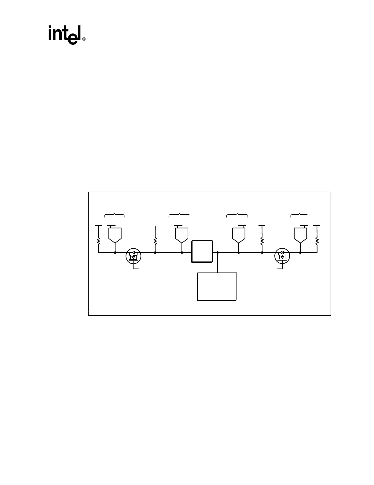
9.8.1.3 High Power/Low Power Mixed Architecture
This design allows for current isolation of high and low current devices while also allowing
SMBus devices to communicate while in S3. V
CC
_
SUSPEND
leakage is minimized by keeping
non-essential devices on the core supply. This is accomplished by the use of a FET to isolate the
devices powered by the core and suspend supplies. See Figure 117.
NOTES:
1. Added considerations for mixed architecture.
2. The bus switch must be powered by V
CC
_SUSPEND.
3. Devices powered by the V
CC
_SUSPEND well must not drive into other devices that are powered off. This is
accomplished with the bus switch.
4. The bus bridge can be a device like the Philips* PCA9515.
9.8.1.4 Calculating the Physical Segment Pull-Up Resistor
The following tables are provided as a reference for calculating the value of the pull-up resistor that
may be used for a physical bus segment. When any physical bus segment exceeds 400 pF, then a
bus bridge device such as the Philips Semiconductor* PCA9515 must be used to separate the
physical segment into two segments that individually have a bus capacitance less than 400 pF.
Figure 117. High Power/Low Power Mixed V
CC
_
SUSPEND
/V
CC
_
CORE
Architecture
B2898-01
Bus
Bridge
Intel
®
6300ESB
I/O Controller
Hub
SMBus
Non-Standby
Devices
Devices running
in Standby
Buffered Power
Good signal from
Power Supply
V
CC
V
CC
V
CC
Sus3_3 V
CC
SusV
CC
Sus
V
CC
Sus3_3
SMBus SMBus
Buffered Power
Good signal from
Power Supply
V
CC
V
CC
Non-Standby
Devices
Devices running
in Standby
LOW CURRENT HIGH CURRENT
 Loading...


