276
Intel
®
855GME Chipset and Intel
®
6300ESB ICH Embedded Platform Design Guide
Schematic Checklist Summary
BCLK,
BCLK#
Refer to the CK409
Checklist for CPU[0],
CPU[0]#, CPU[1],
CPU[1]#, CPU[2], and
CPU[2]#.
Connect to CK409.
HDSTBN[3:0]# Connect directly to processor (DSTBN[3:0]# signals).
HDSTBP[3:0]# Connect directly to processor (DSTBP[3:0]# signals).
DINV[3:0]# Connect directly to processor (DINV[3:0]# signals).
CPURST#
220
Ω 6% pull-up to
VCCP. 22.6
Ω 1%
series to ITP (pin 12).
Refer to the Pentium
®
M
Processor Checklist for
RESET#.
Connect to processor (RESET# signal) and ITP (if
implemented).
HD[63:0]# Connect directly to processor (D[63:0]# signals).
DPWR# Connect directly to processor (DPWR# signal).
DPSLP#
1KΩ pull-up to VCCP at
GMCH.
4.7 K
Ω pull-up to VCCP
at CPU.
Used only with the ICH4-M.
The 6300ESB does not provide this signal.
HXSWING
301
Ω 1% pull-up to
VCCP
150
Ω 1% pull-down to
GND
Signal voltage level = 1/3 of VCCP. C1a = 0.1 µF.
C1b=0.1 µF.
Refer to Figure 151.
HYSWING
301
Ω 1% pull-up to
VCCP
150
Ω 1% pull-down to
GND
Signal voltage level = 1/3 of VCCP. C1a=0.1 µF.
C1b=0.1 µF.
Refer to Figure 151.
HXRCOMP
27.4
Ω 1% pull down to
GND
One pull-down resistor where trace shall be 10 mil wide
with 20 mil spacing. Refer to Section 4.8.3.2.
HYRCOMP
27.4
Ω 1% pull down to
GND
One pull-down resistor where trace shall be 10 mil wide
with 20 mil spacing. Refer to Section 4.8.3.2.
HDVREF[2:0]
49.9
Ω 1% pull-up to
VCCP
100
Ω 1% pull-down to
GND
Signal voltage level = 2/3 of VCCP. Need one 0.1 µF cap
and one 1 µF cap near voltage divider.
HAVREF
49.9
Ω 1% pull-up to
VCCP
100
Ω 1% pull-down to
GND
Signal voltage level = 2/3 of VCCP. Need one 0.1 µF cap
and one 1 µF cap for voltage divider.
HCCVREF
49.9
Ω 1% pull-up to
VCCP
100
Ω 1% pull-down to
GND
Signal voltage level = 2/3 of VCCP. Need one 0.1 µF cap
and one 1 µF cap for voltage divider.
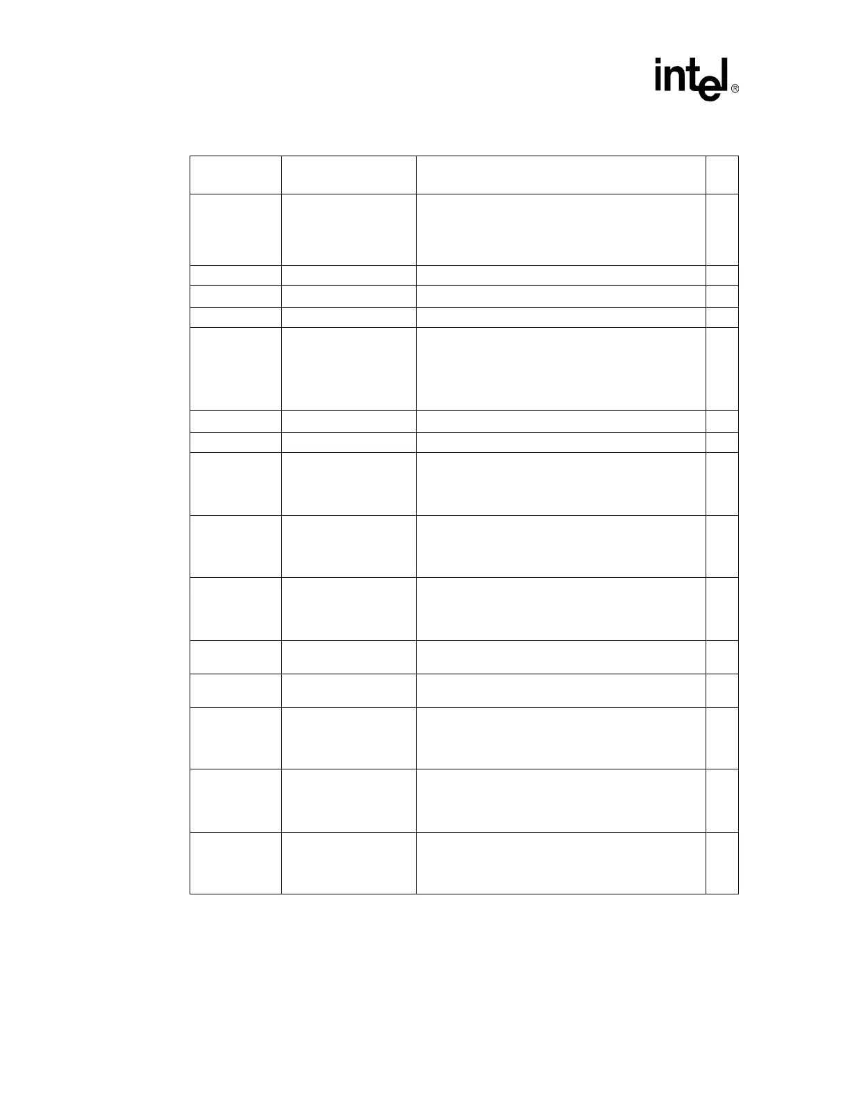
Table 124. FSB Checklist (Sheet 2 of 2)
Pin Name
System
Pull-up/Pull-down
Notes
√