Model 2701 User’s Manual Basic DMM Operation 3-41
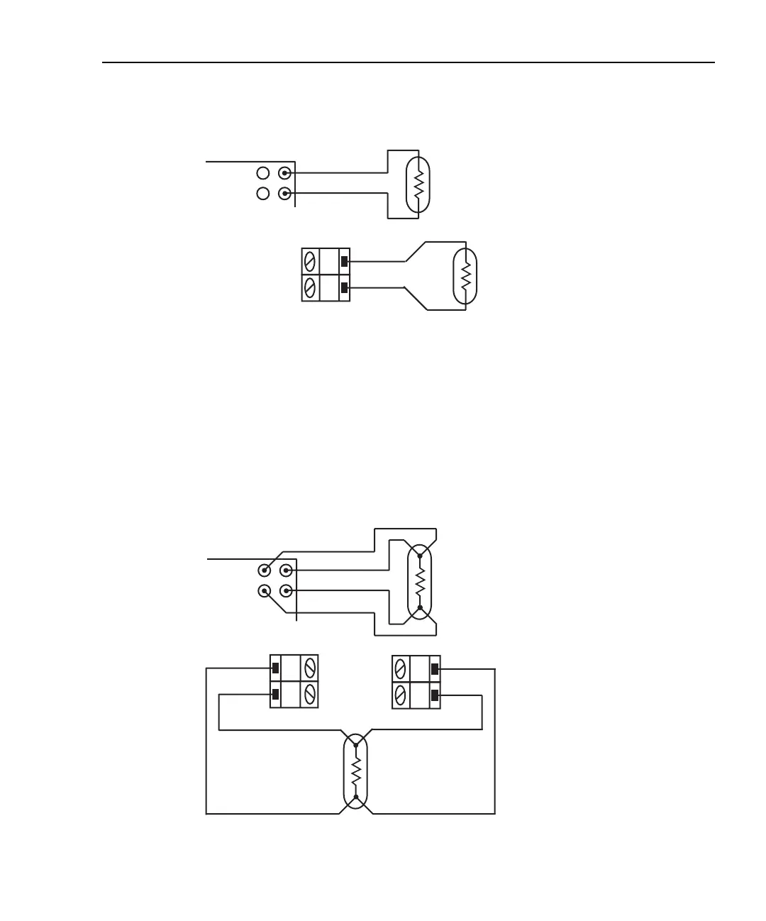
Figure 3-15
Thermistor connections
4-wire RTD connections
Shown in Figure 3-16 are 4-wire RTD connections to the Model 2701. For the Model 7700
switching module, paired channels are used to perform the 4-wire measurement. The two
input leads of the RTD are connected to a primary channel (1 through 10), while the two
sense leads are connected to its paired channel (11 through 20). Channel 1 is paired to
channel 11, channel 2 is paired to channel 12, and so on.
Figure 3-16
4-wire RTD connections
Model 2701
Input HI
Input LO
A. Front panel inputs
Thermistor
B. Model 7700 switching module
H
L
CH 1-20
Model 7700
Switching
Module
Thermistor
Model 2701
Input HI
Input LO
Sense HI
Sense LO
4-wire
RTD
A. Front panel inputs
4-wire
RTD
B. Model 7700 switching module
H
L
CH 1-10
Model 7700
Switching
Module
H
L
CH 11-20
INPUT
SENSE
Input High
Sense High
Input LowSense Low

 Loading...


