11-8 Status Structure Model 2701 User’s Manual
Status byte and service request (SRQ)
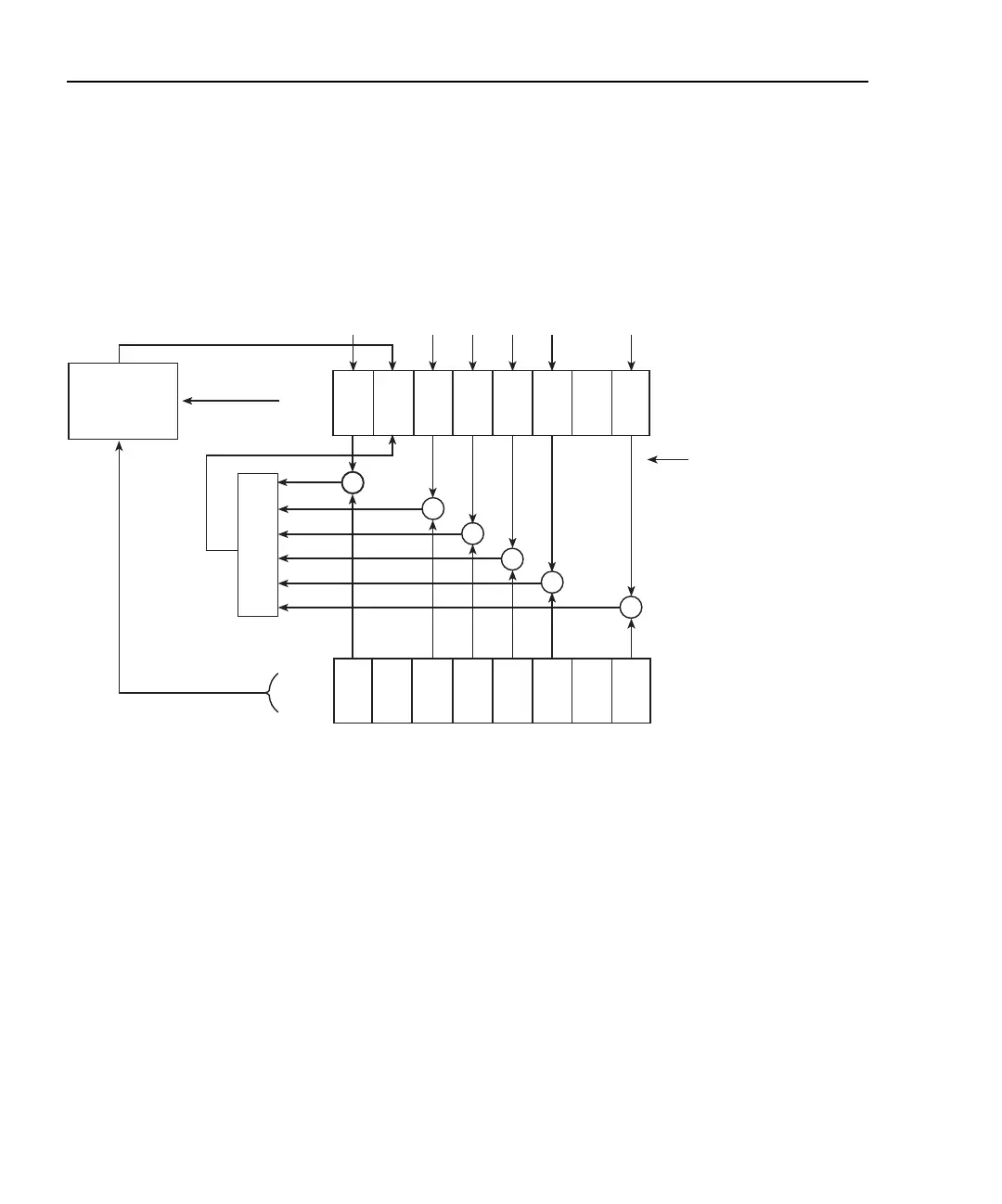
Service request is controlled by two 8-bit registers: the Status Byte Register and the
Service Request Enable Register. Figure 11-3 shows the structure of these registers.
Figure 11-3
Status byte and service request (SRQ)
Status byte register
The summary messages from the status registers and queues are used to set or clear the
appropriate bits (B0, B2, B3, B4, B5, and B7) of the Status Byte Register. These summary
bits do not latch and their states (0 or 1) are solely dependent on the summary messages (0
or 1). For example, if the Standard Event Register is read, its register will clear. As a result,
its summary message will reset to 0, which in turn will reset the ESB bit in the Status Byte
Register.
OR
(B6)
Status Summary Message
Read by *STB?
OSB = Operation Summary Bit
MSS = Master Summary Status
ESB = Event Summary Bit
Mav = Message Available
Service Request
Enable Register
(B1)
__
____
&
*SRE
*SRE?
Status Byte
Register
Service
Request
Generation
*STB?
MSS
(B6)
MSB
(B0)
EAV
(B2)
QSB
(B3)
MAV
(B4)
ESB
(B5)
OSB
(B7)
(B1)
MSB
(B0)
EAV
(B2)
QSB
(B3)
MAV
(B4)
ESB
(B5)
OSB
(B7)
QSB = Questionable Summary Bit
EAV = Error Available
MSB = Measurement Summary Bit
& = Logical AND
OR = Logical OR
&
&
&
&
&