Model 2701 User’s Manual Range, Digits, Rate, Bandwidth, and Filter 4-15
NOTE While the filter processes readings, the FILT annunciator blinks. Readings that
are being displayed while the FILT annunciator blinks are not final filtered read-
ings. When the FILT annunciator stops blinking, the filter has settled.
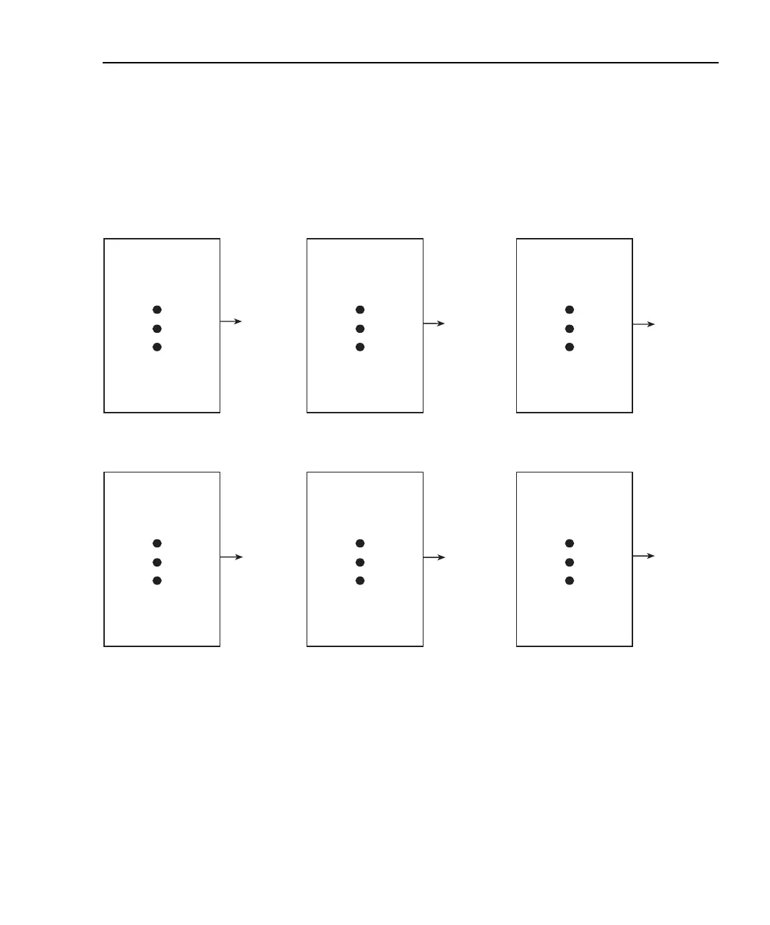
Figure 4-2
Moving and repeating filters
Filter window
The digital filter uses a “noise” window to control filter threshold. As long as the input
signal remains within the selected window, A/D conversions continue to be placed in the
stack. If the signal changes to a value outside the window, the filter resets and the filter
starts processing again starting with a new initial conversion value from the A/D converter.
The noise window, which is expressed as a percentage of range (or maximum temperature
reading), allows a faster response time to large signal step changes (e.g., scanned
readings). A reading conversion outside the plus or minus noise window fills the filter
stack immediately.
Conversion #10
#9
#8
#7
#6
#5
#4
#3
#2
#1
Conversion
Average
Reading
#1
Conversion #12
#11
#10
#9
#8
#7
#6
#5
#4
#3
Conversion
Average
Reading
#3
Conversion #11
#10
#9
#8
#7
#6
#5
#4
#3
#2
Conversion
Average
Reading
#2
A. Type - Moving Average, Readings = 10
Conversion #10
#9
#8
#7
#6
#5
#4
#3
#2
#1
Conversion
Average
Reading
#1
Conversion #20
#19
#18
#17
#16
#15
#14
#13
#12
#11
Conversion
Average
Reading
#2
Conversion #30
#29
#28
#27
#26
#25
#24
#23
#22
#21
Conversion
Average
Reading
#3
B. Type - Repeating, Readings = 10

 Loading...


