8-4 Triggering Model 2701 User’s Manual
Scanning — When scanning, the nominal delay will be long enough to allow each switch-
ing module channel relay to settle before making the measurement. When scanning, the
auto delay times in Table 8-1 are valid for all control sources.
The delay function is accessed by pressing SHIFT and then DELAY. The present delay
setting (AUTO or MANual) is displayed. Press the
or key to display the desired
setting and press ENTER.
If MANual is chosen, also enter the duration of the delay in the hour/minute/second
format using the , , , and keys. The maximum is 99H:99M:99.999S:. Note that
pressing the AUTO key sets the delay to 0.001 sec. Press ENTER to accept the delay or
EXIT for no change.
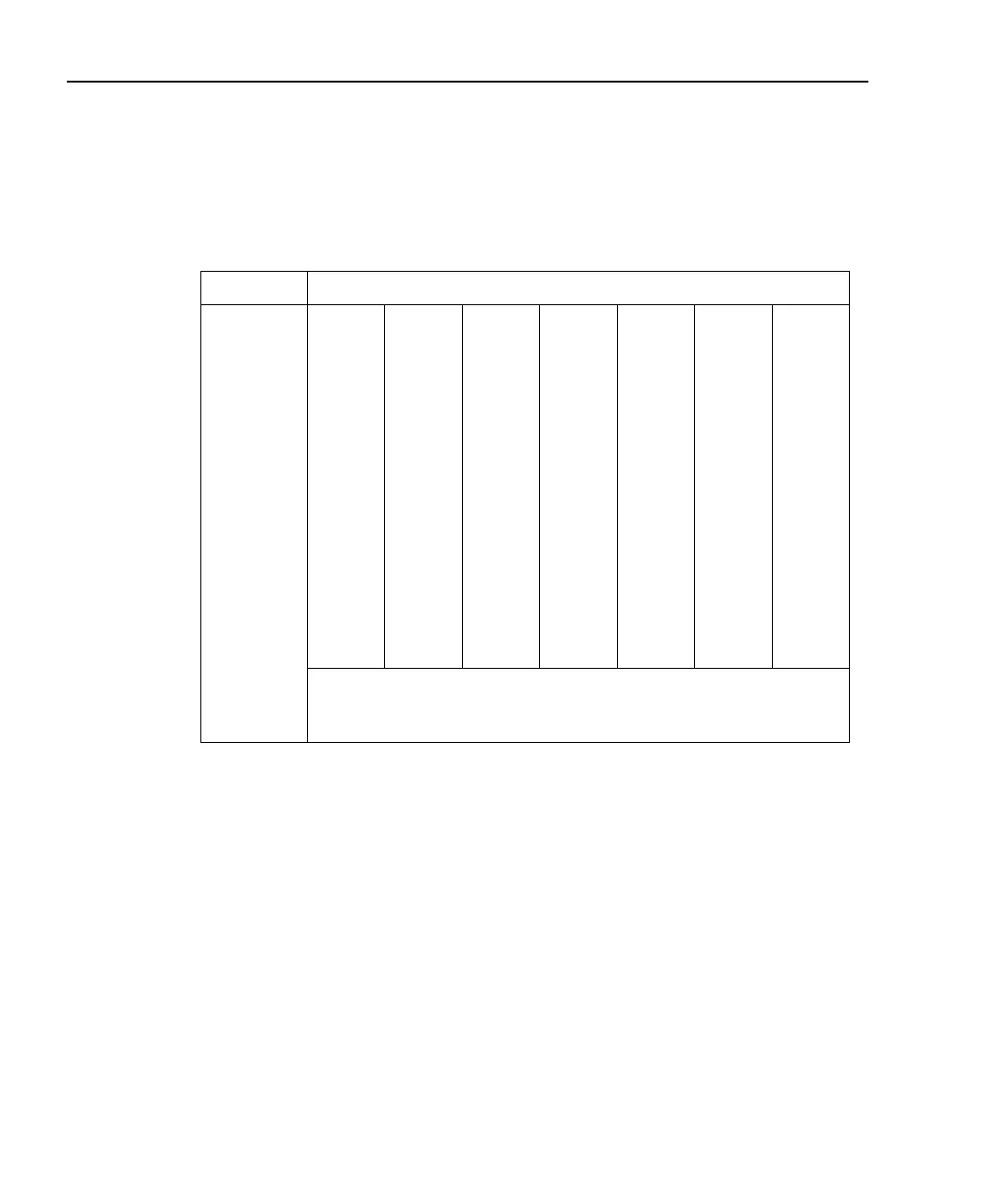
Table 8-1
Auto delay settings
Function Range and delay
DCV 100mV
1ms
1V
1ms
10V
1ms
100V
5ms
1000V
5ms
ACV 100mV
25ms
1V
25ms
10V
25ms
100V
25ms
750V
25ms
FREQ and
PERIOD
100mV
1ms
1V
1ms
10V
1ms
100V
1ms
750V
1ms
DCI 20mA
2ms
100mA
2ms
1A
2ms
3A
2ms
ACI 1A
400ms
3A
400ms
Ω2, Ω4 100Ω
3ms
1kΩ
3ms
10kΩ
13ms
100kΩ
25ms
1MΩ
100ms
10MΩ
150ms
100MΩ
250ms
Continuity 1kΩ
3ms
TEMP The auto delay for thermocouples is 1ms. For thermistors and 4-wire
RTDs, the auto delay period is the same as the delay for the resistance
range that is used for the measurement.

 Loading...


