Model 2701 User’s Manual Close/Open Switching Module Channels 2-31
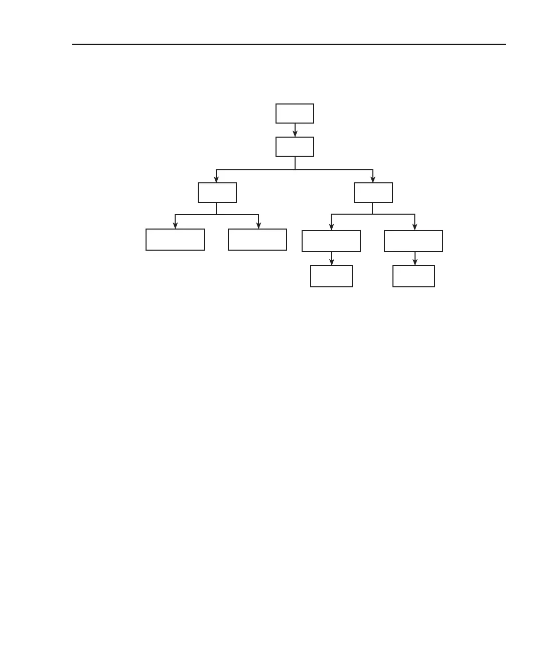
Figure 2-11
CARD menu tree
CARD: CONFIG — This menu item is used to configure switching modules. The
channels of the Model 7700 switching module and other similar type modules do not need
to be configured.
SLOTX: 77XX — Use to configure the switching module in Slot X (where X = 1 or 2). If
configuration is not necessary, the instrument will exit from the menu when ENTER is
pressed.
NOTE For switching modules that require configuration, refer to packing list that was
shipped with each module.
CARD: VIEW — This menu item is used to view all analog input channels that are
presently closed. These include both measurement and non-measurement channels.
The channels are built into a string that scrolls the display. Four dots identify the end of the
string. Model 7700 example (Slot 1) — Assume the Ω4 function is selected and system
channel 101 is closed. The following string will scroll across the display:
101, 111, 123, 124, 125 . . . .
Channels 101 and 111 are the paired channels for the 4-wire measurement. Channel 123 is
the 4-pole relay setting, and channels 124 and 125 connect input and sense to the DMM of
the Model 2701 (Figure 2-2).
NOTE Some switching modules have analog outputs, digital inputs, and/or digital
outputs. The values for these channels are also displayed from the VIEW menu
item. For details on a particular switching module, refer to the packing list that
was shipped with each module.
SHIFT
CARD
CONFIG
VIEW
Scrolls
Channels
Scrolls
Channels
SLOT1: 77XX SLOT2: 77XX
77XX = Model number of installed
switching module.
SLOT1: 77XX
SLOT2: 77XX

 Loading...


