9-6 Limits and Digital I/O Model 2701 User’s Manual
Digital outputs
The digital I/O port has five digital outputs. Each digital output can be used as a sink to
control devices (e.g., relays) or as a source to provide input to external logic (TTL or
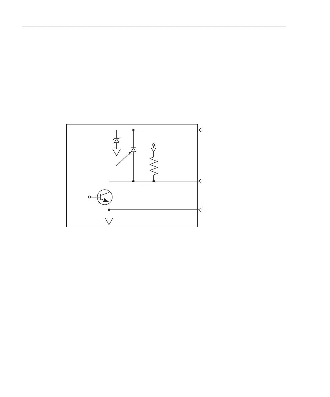
CMOS) circuitry. The simplified schematic for the digital outputs are shown in Figure 9-3.
Note that this illustration shows the schematic for one digital output. All five digital output
circuits are identical.
Figure 9-3
Digital I/O port simplified schematic
The five digital output lines (pins 1 through 5) are controlled by limit operations. Each of
these five outputs correspond to the following limit operations:
Digital Output 1 - Low Limit 1 (LO1)
Digital Output 2 - High Limit 1 (HI1)
Digital Output 3 - Low Limit 2 (LO2)
Digital Output 4 - High Limit 2 (HI2)
Digital Output 5 - Master Limit (logical OR of the four above limits)
When a limit (LO1, HI2, LO2, HL2) is reached, the digital output line for that limit will be
pulled high or low. When a reading is within the limit, the output line is released. Digital
output 5 is the logical OR of the four limits. Therefore, if any of the four limits are reached
or exceeded, output 5 will be pulled high or low.
NOTE When the reading is taken and a limit has been reached, there is a short delay
before the digital output line is active. As measured from the output trigger
(TLINK), the delay is about 10msec when closing a channel and about 2msec
without a channel closure. Because of additional time needed for data
conversion, the delay can be up to 10 times longer for temperature readings.
Allow for this delay when designing test systems.
+5V
4.75kW
(Pull-up)
Pin 9 - Digital Ground
Digital Output
Pin 7 (+5V to +33V)
Digital Output
Flyback Diode
Control
Line
33V
Model 2701

 Loading...


