2-8 Close/Open Switching Module Channels Model 2701 User’s Manual
2-wire functions
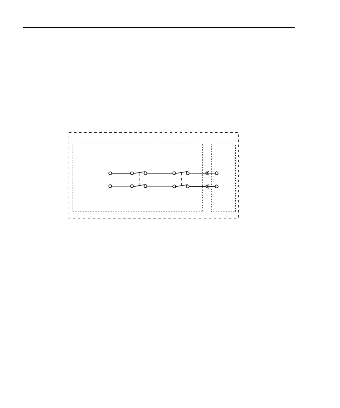
Figure 2-1 shows an example of how the system channel is connected to the DMM Input
of the Model 2701. Assume a Model 7700 switching module is installed in slot 1 of the
mainframe. When channel 101 is closed using the system channel close keys, both the
Channel 1 relay and the backplane isolation relay (Channel 25) close to connect the
channel to the DMM. The complete simplified schematic of the Model 7700 is provided in
Figure 2-12.
Figure 2-1
2-wire system channel connections to Model 2701 DMM
DMM
Model 7700 Switching Module
Model 2701
Slot 1
System channel operation:
Close channel 101
Channel 1
Relay
HI
LO
HI
LO
Input
Channel 25
Backplane
Isolation
Relay
Channel 1

 Loading...


