9-2 Limits and Digital I/O Model 2701 User’s Manual
Limits
NOTE Limits cannot be used with the CONT function.
When using limits, you can set and control the values that determine the HIGH/IN/LOW
status of subsequent measurements. The limit test is performed on the result of an enabled
Rel, Math, Ratio, or Channel Average operation.
NOTE The various instrument operations, including Limits, are performed on the input
signal in a sequential manner. See “Signal processing sequence,” page D-2, for
details. It includes flow charts showing where in the processing sequence that
Limits are tested.
There are two sets of limits. Limit 1 uses high and low limits (HI1 and LO1), as does
Limit 2 (HI2 and LO2). The HIGH/IN/LOW status indication applies to the first limit
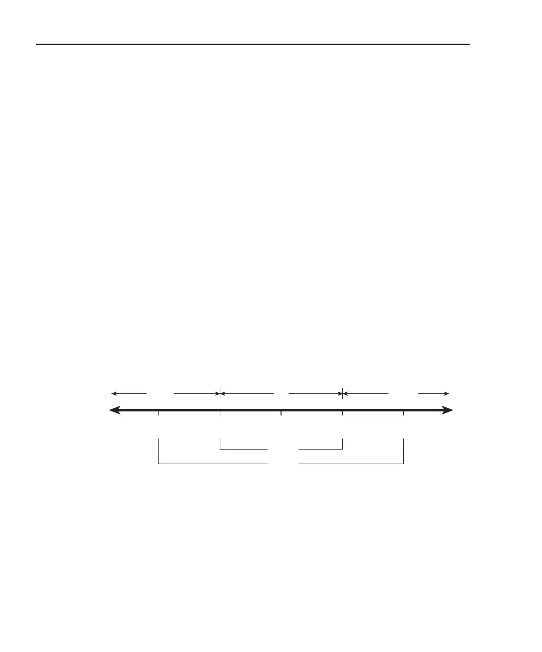
(limit 1 or limit 2) that fails. Figure 9-1 illustrates the following limits which are the
factory defaults:
Limit 1: HI1 = +1V and LO1 = -1V
Limit 2: HI2 = +2V and LO2 = -2V
Keep in mind that a limit value for Limit 2 does not have to exceed the Limit 1 value. For
example, Limit 2 can be set to ±1V and Limit 1 can be set to ±2V. In this case, Limit 2 will
fail before Limit 1.
Figure 9-1
Default limits
When a reading is within both limits, the message “IN” will be displayed. When the read-
ing is high or low, the HIGH or LOW annunciator turns on and the number “1” or “2” will
replace the “IN” message. A “1” indicates that Limit 1 has failed, while “2” indicates that
Limit 2 has failed. However, if the reading is outside both limits, the number “1” will be
displayed.
For the limits shown in Figure 9-1, a reading of +1.5V is outside Limit 1, but inside
Limit 2. The HIGH annunciator will turn on and display the number “1.” For a reading of
+2.5V, which is outside both Limit 1 and Limit 2, the same status indication (HIGH, “1”)
will be displayed since Limit 1 takes precedence.
0V
1V 2V
-2V
-1V
LO2
LO1 HI1 HI2
Limit 1
Limit 2
LOW
IN
HIGH

 Loading...


