G-6 KE2700 Instrument Driver Examples Model 2701 User’s Manual
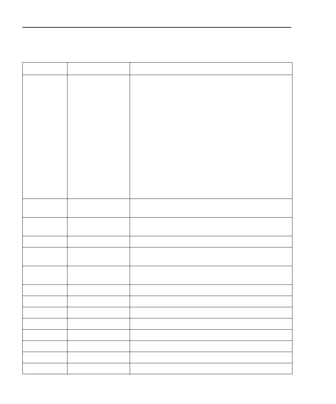
Name Manual Reference Brief Description
Advance8 None Use Case 8 — 7706 module in slot 1 and 7702 module in slot 2:
• 7706 module:
• Output analog output values to analog output channels.
• Output digital output values to digital output channels.
• 7702 module:
• Scan 120 DCV channels.
• Measurement speed (rate) – 1 plc.
• Filter – Disabled (no filtering).
• Math – mX+b, m = 0.555, b = -17.778.
• Limits – Limit 1 (all channels) = 100, Limit 2 = 180.
• Buffer – Store 320 reading strings. Buffer elements include
reading, channel #, and limit code.
• Triggering – Bus control source, trigger delay 0.125 seconds.
• Data retrieval – SRQ when buffer ¼, ½, ¾, and full.
Analout See 7706 packing list Demonstrates setting the output value of the analog output
channels of the 7706 module.
AOCalibration See 7706 packing list Demonstrates how to remotely calibrate the analog output
channels of the 7706 module.
BufStats Page 6-15 (Prog Ex.) Demonstrates calculating the mean of 20 readings.
BusTrg Page 12-7
(*TRG Prog Ex.)
Demonstrates use of bus triggering.
CloseChannels Page 2-21
(Remote Prog Ex.)
Demonstrates closing channels – multiple channel operation.
ConfigChan Page 3-58 (Ex. 4) Demonstrates configuring channels.
CTMMV Page 3-57 (Ex. 1) Demonstrates continuous AC volts measurement.
Digits Page 4-7 (Ex. 1 & 2) Demonstrates setting display resolution.
Digout See 7706 packing list Demonstrates setting the digital outputs on a 7706 module.
Get1Reading None Demonstrates retrieving one reading from the instrument.
Limits Page 9-14 Demonstrates limits and digital outputs.
Linear Page 5-14 (Ex. 1) Demonstrates an mX+b linear calculation.
MAFilter Page 4-22 (Ex. 1) Demonstrates moving filter use.
Table G-1 (continued)
Visual Basic and CVI (C) examples

 Loading...