Technical data
Rated data
Overcurrent operation
3
139
EDKVS9332X DE/EN/FR 8.0
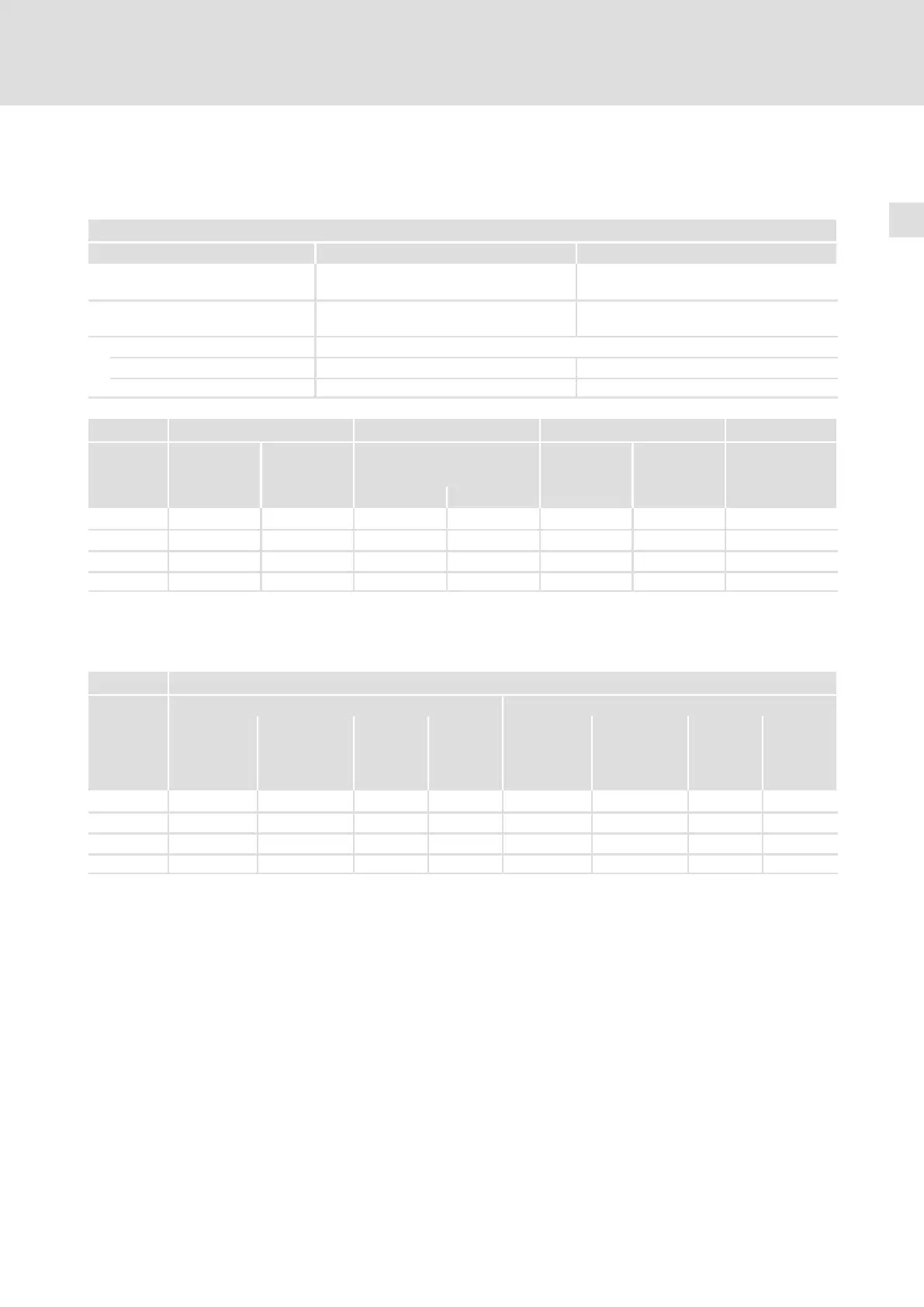
3.3.3 Overcurrent operation
3.3.3.1 Operation at 400 V
Basis of the data
Voltage Frequency
AC mains connection [V
rate
d
]
3/PE AC 320 V − 0 % ... 440 V + 0 %
45 Hz − 0 % ... 65 Hz + 0 %
DC−mains connection
(alternatively)
[U
DC
] DC 450 V − 0 % ... 620 V + 0 % ˘
Output voltage
With mains choke 3 ~ 0 approx. 94 % V
rated
˘
Without mains choke 3 ~ 0 ... U
N
˘
9300 Mains current
1)
Typical motor power Output power Power loss
With
mains choke
Without
mains choke
ASM
(4−pole)
8 kHz
2)
U, V, W +U
G
, −U
G
3)
Type I
r
[A] I
r
[A] P
r
[kW] P
r
[hp] S
r8
[kVA] P
DC
[kW] P
V
[W]
EVS9321−xx 1.5 2.1 0.37 0.5 1.0 2.0 100
EVS9322−xx 2.5 3.5 0.75 1.0 1.7 0.75 110
EVS9323−xx 3.9 5.5 1.5 2.0 2.7 2.2 140
EVS9324−xx 7.0 ˘ 3.0 4.0 4.8 0.75 200
Bold print = Lenze setting
1)
Mains currents at 8 kHz switching frequency
2)
Switching frequency of the inverter
3)
Power which can additionally be drawn from the DC bus at operation with power−adapted motor
9300 Output currents
8 kHz
1)
16 kHz
1)
Rated current Continuous
thermal
current
3)
Maximum
current
2)
Standstill
current
Rated current Continuous
thermal
current
3)
Maximum
current
2)
Standstill
current
Type I
r8
[A] I
r8
[A] I
M8
[A] I
08
[A] I
r16
[A] I
r16
[A] I
M16
[A] I
016
[A]
EVS9321−xx 1.5 1.05 3.0 3.0 1.1 0.77 2.2 2.2
EVS9322−xx 2.5 1.75 5.0 5.0 1.8 1.26 3.6 3.6
EVS9323−xx 3.9 2.73 7.8 7.8 2.9 2.03 5.8 5.8
EVS9324−xx 7.0 4.9 14.0 14.0 5.2 3.64 10.4 10.4
1)
Switching frequency of the inverter
2)
The currents apply to a periodic load change cycle with max. 10 seconds overcurrent duration and 50 seconds base
load duration at max. 44 % of the rated current
3)
70 % of the rated current
 Loading...


