Electrical installation
Standard devices in the power range 55 ... 75 kW
Mains connection, DC supply
5
191
EDKVS9332X DE/EN/FR 8.0
5.7.2 Mains connection, DC supply
Note!
ƒ If a mains filter or RFI filter is used and the cable length between mains/RFI
filter and drive controller exceeds 300 mm, install a shielded cable.
ƒ For DC−bus operation or DC supply, we recommend using shielded DC
cables.
PE
+UG -UG
L1 L2
L3
3
01 2
L1, L2, L3
+U , -U
PE
GG
M10
30 Nm
264 lb-in
}
+
PE
9300vec127
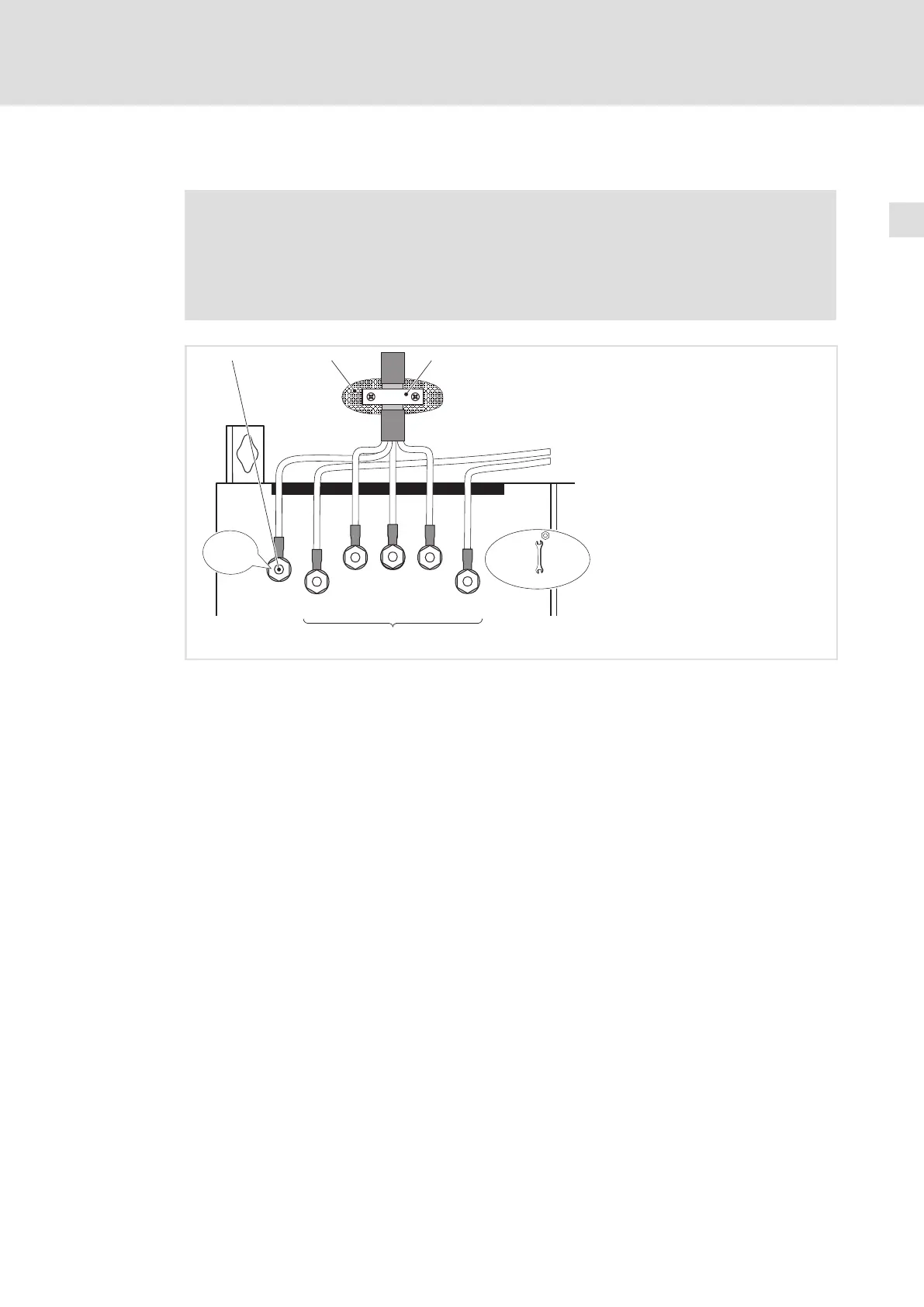
Fig. 5−20 Mains connection, DC supply for 55 ... 75 kW drive controller
PE stud
Connect PE cable with ring cable lug
Conductive surface
Shield clamp
Place shield with large surface on control cabinet mounting plate and fasten with shield
clamp (shield clamp is not part of the scope of supply)
To improve the shield connection, also place the shield on the PE stud
Mains and DC bus connection
L1, L2, L3: Connection of mains cable with ring cable lugs
+U
G
, −U
G
: Connection of DC−bus components or connection of the controller in the DC−bus
system (see system manual)
 Loading...


