Electrical installation
Wiring of the feedback system
SinCos encoder at X8
5
213
EDKVS9332X DE/EN/FR 8.0
5.10.4 SinCos encoder at X8
Technical data
Field Values
Connection at drive controller Connector: Pin, 9−pole, Sub−D
Connectable SinCos encoders l SinCos encoders with a rated voltage from 5 V... 8 V.
l SinCos encoder of the company Stegmann with Hiperface
®
interface,
Stegmann type SCS/SCM (prolongs the initialisation time of the
controller to approx. 2 seconds)
Sine and cosine track voltage 1 V
ss
±0.2 V
Voltage RefSIN and RefCOS +2.5 V
Internal resistance R
i
221 W
Internal voltage source
(X8/4, X8/5)
5 V DC / max. 200 mA
Wiring
SIN
COS
0.5 V
0.5V
RefCOS
RefSIN
= 2.5 V
= 2.5 V
SIN
V
CC
GND
Z
+KTY
-KTY
1
2
3
4
5
6
7
8
9
COS
X8
l<50m
RefCOS
RefSIN
Z
KTY
9300STD330
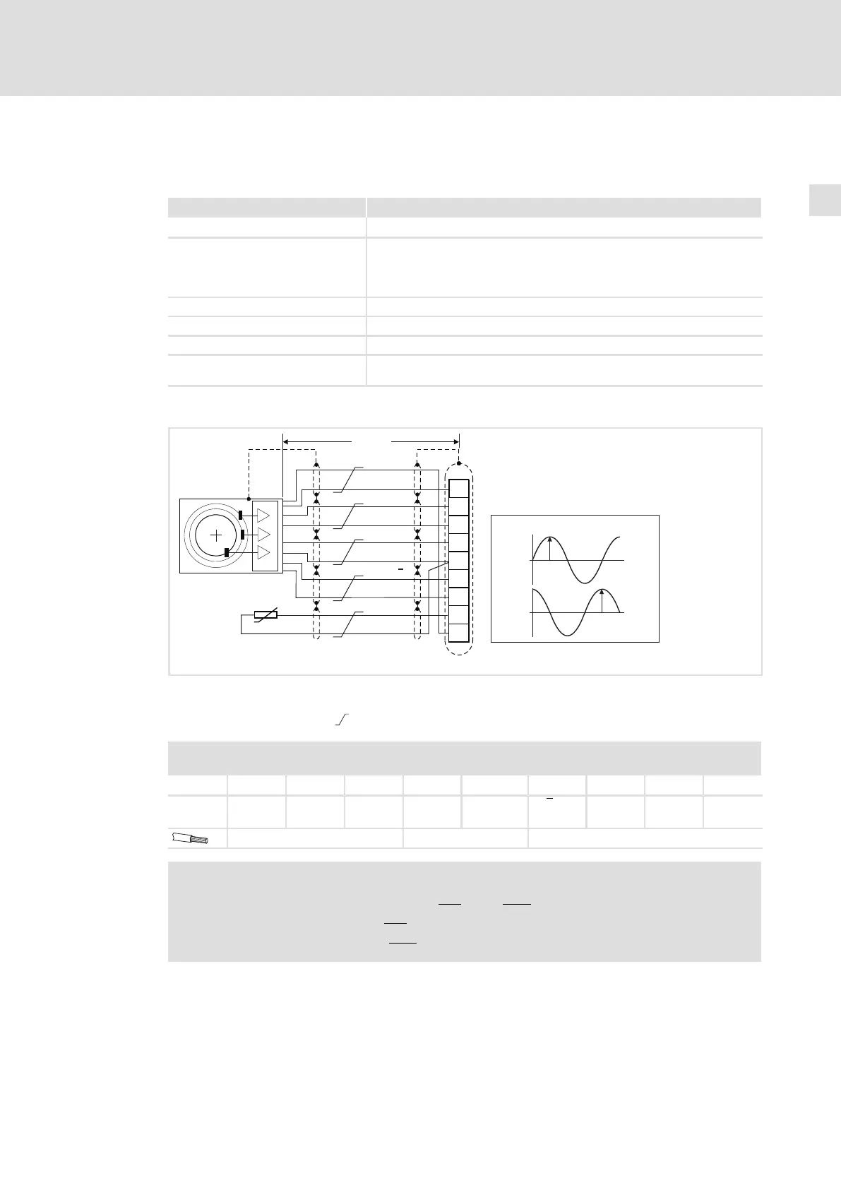
Fig. 5−34 SinCos encoder connection
Signals for CW rotation
Cores twisted in pairs
X8 − SinCos encoder
Connector: Pin, 9−pole, Sub−D
Pin 1
2 3 4 5 6 7 8 9
Signal SIN RefCOS COS V
CC
GND (−KTY) Z or
−RS485
Z or
+RS485
+KTY RefSIN
0.14 mm
2
(AWG 26) 1 mm
2
(AWG 18) 0.14 mm
2
(AWG 26)
Note!
ƒ For encoders with tracks SIN, SIN, COS, COS:
– Assign RefSIN with SIN
.
– Assign RefCOS with COS
.
 Loading...


