OPERATING PROCEDURES TMS9000-2 OPERATOR MANUAL
4-70
Published 02-21-2019, Control # 611-05
Locking the telescopic section
Every telescopic section can be locked at the fixed lengths,
refer to Fixed length, intermediate length, telescoping length,
page 4-63.
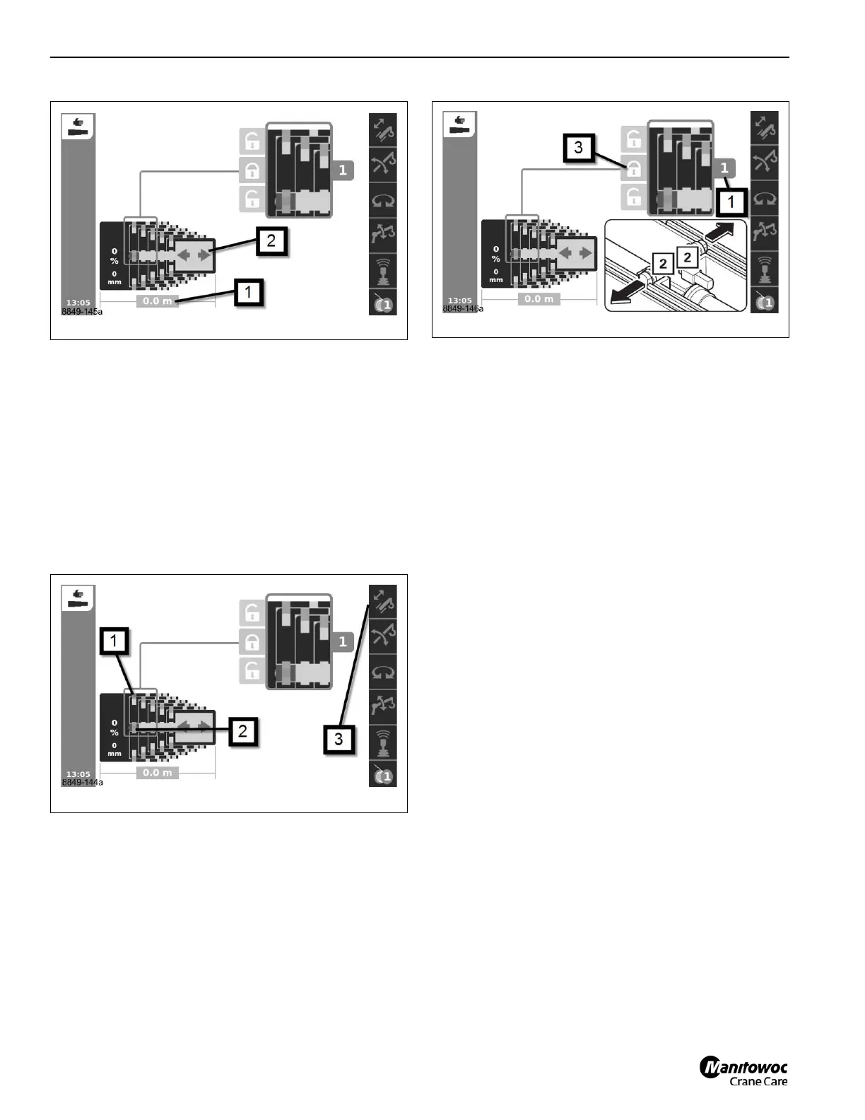
Prerequisites
Telescoping mechanism on – symbol (3, Figure 4-136) green
Telescopic section unlocked – symbol (1) red
Telescoping cylinder locked – symbol (2) green.
Lock
• Telescope to the desired fixed length, e. g. telescopic
section (1, Figure 4-137) 1 to 100%.
If the symbol (4) is displayed, the telescopic section must be
locked.
• Select the symbol (3).
• Confirm the selection – the locking pins will extend –
symbol (2) green.
Locking the telescopic section for on-road driving
Once you have retracted the main boom, you might lock the
telescoping cylinder in telescopic section I to achieve the
proper axle loads.
Telescoping with semi-automation
When telescoping with semi-automation (or the semi-auto
mode), the operator enters, on the display, the pinning
location for each of the boom sections (a target or requested
“tele picture”). If this pinning configuration is accepted by
CCS, then the joystick controller is used to move the boom
sections to the pre-determined configuration. The
telescoping cylinder moves between the boom sections
automatically as needed.
NOTE: The entered boom configuration (“tele picture”)
does not have to be completed for normal
operation of the boom. For instance, if the
requested boom configuration is 100-100-0-0-0,
and just the T2 section is locked at 100% (T1
section still at 0%), then the boom can be operated
as if the configuration 0-100-0-0-0 was entered.
The operator can just stop the telescoping function
with the boom at 0-100-0-0-0.
If the boom is desired to be fully or partially
retracted after just reaching 0-100-0-0-0 (and when
100-100-0-0-0 had originally been entered), the
operator can just reverse the direction of the
joystick and the boom will retract. That is, it is not
necessary to enter a boom configuration of 0-0-0-
0-0 to retract the boom. The entered boom
configuration (target or requested “tele picture”) is
ALWAYS only a final destination or configuration.
The joystick is ALWAYS used to indicate extending
or retracting the boom itself, NEVER to indicate the
extending or retracting of the telescoping cylinder.
The allowed motion for the boom with the joystick is
indicated by arrows shown on the display. The
telescoping direction arrow to the right is always

 Loading...


