Revision:1.0(2023-01-12)
200
1. Refer to the disassembly procedures in 7.2.2 Disassembly and Assembly and 7.7.2 Disassembly
and Assembly
to remove the Display Assembly and the main unit front cover.
2. Remove the cables between the Display Rotatory Assy(With conversion board) and the main
unit as follows:
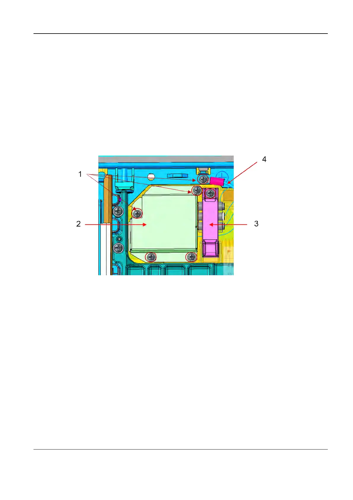
a. Remove the four Phillips pan-head screws of the outlet shielding cover of the main unit, and
take off the outlet shielding cover of the main unit.
b. Remove one Phillips pan-head screw of the cable crimp and take off the cable crimp.
c. Remove one Phillips pan-head screw of the ground terminal and take off the ground
terminal.
1 Six Phillips pan-head screws (M3)
2 Outlet shielding cover of the main unit
3 Cable crimp
4 Grounding terminal
3. Remove the HDMI, power supply, and control cable terminals.
Diagnostic Ultrasound System
Service Manual
7 FRU Replacement
 Loading...


