Revision:1.0(2023-01-12)
140
Parame-
ter
F SVD SV Angle
Descrip
tion
Transmis
sion
frequency
SV depth SV size Correction angle
Parameters that can be adjusted to optimize the PW/ CW mode image are indicated in the
following.
Adjustment method Parameter
Adjustment in the image area Gain, Depth, iTouch, TGC, and Image quality
Adjustment in the image menu Quick Steer, Display Format, Auto Calc, Auto
Calculation Parameter, Auto Invert, 2/3 Filter,
Wall Filter, Speed (mm/s), Scale (cm/s), Calc
Cycle, Rotation, Tint Map, A. Power (%),
Dynamic Range, Gray Map, T/F Res, Colorize,
HPRF, Volume, Dual, Quick Steer, Trace Area,
Trace Sensitivity, and Trace Smoothness
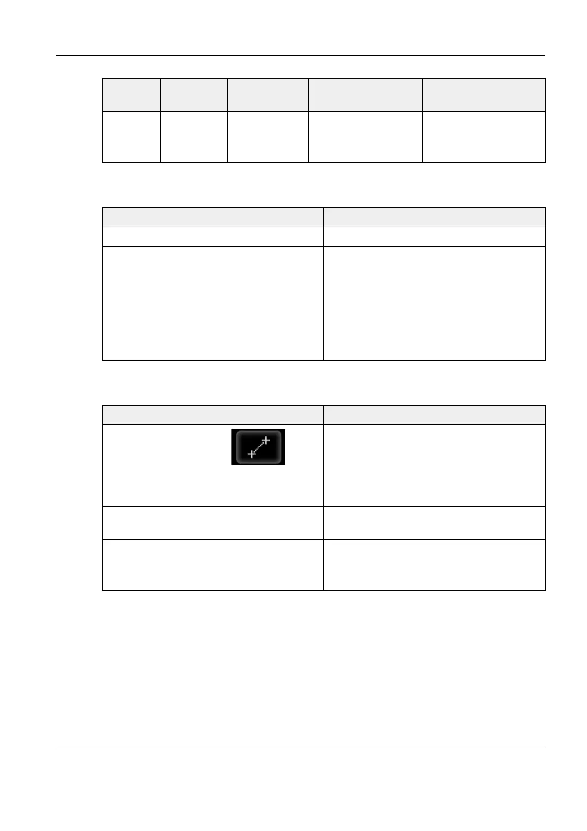
44..44..22..22 Checking Basic Measurements
Procedure Acceptance criteria
In B imaging mode, tap the
icon in
the lower left part of the image area.
By default, the 2D basic measurement
function is accessed. Tap any one or two
measurement items (such as length and
area). The measurement or calculation results
are displayed below the image in real time.
Tap the same icon again. The system exits the corresponding
measurement state.
Perform similar operations in other imaging
modes.
The application measurement function maps
different application software packages.
Perform operations selectively.
Diagnostic Ultrasound System
Service Manual
4 Function and Performance
Check
 Loading...


