Revision:1.0(2023-01-12)
54
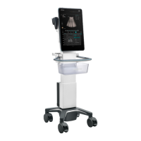
The following figure shows the interconnection among modules in the charging pile and the
wireless charging receiving module.
Charging pile:
1. The wireless charging transmitting module (including the transmitting coil) converts the DC
power supply into the transmission power supply.
2. The AC-DC power module converts the mains supply into each DC power supply used by the
charging pile.
3. The alignment control board provides the alignment control and visual and audible indication
functions.
4. The wireless charging indicator board shows the charging LED lights.
5. The wireless charging USB upgrade and sensor calibration board provides the functions of
upgrading the charging pile firmware and calibrating the alignment algorithm sensor.
Wireless receiving module:
1. The wireless charging receiving module (including the receiving coil) receives the transmission
power supply from the charging pile, converts it through rectification and voltage reduction, and
generates the DC power supply for charging the battery of the ultrasound trolley.
2. The control board of the wireless charging mains supply provides the function of mutual
exclusion between the ultrasound trolley mains supply input and the wireless charging input
(the trolley mains supply has a higher priority).
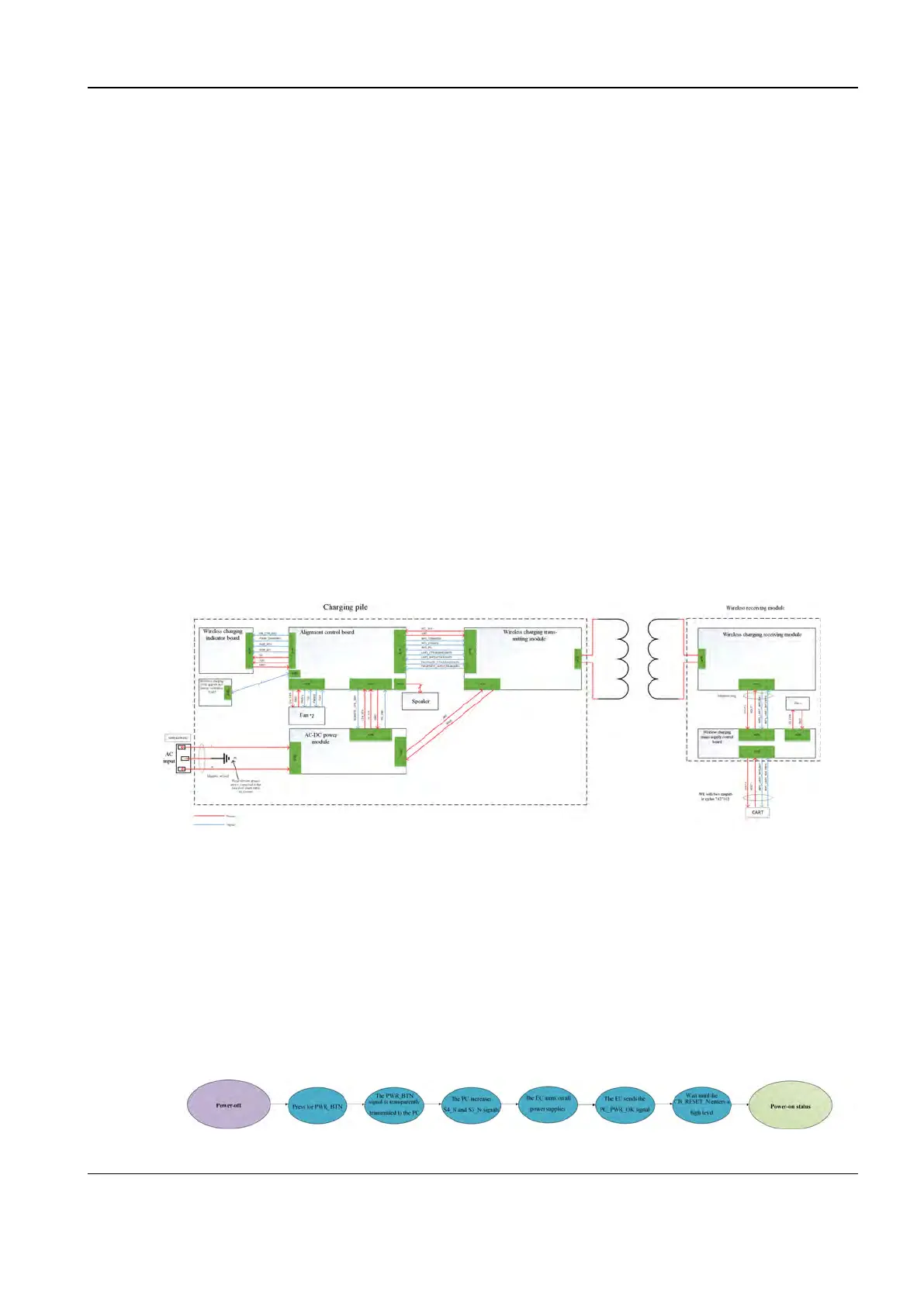
22..33..88..77 Timing Sequence of System Power-on and Power-Off
AC power-on
With AC, 5VSTB is always enabled for the EC firmware. After being dejittered, the PWR_BTN
signal only needs to be transferred to the PC, which then increases S4_N and S3_N signals.
Then the EC firmware controls power-on by each power supply, and then sends the PC_PWR_
OK signal. When CB_RESET changes to a high level, the PC module enters the power-on state.
Figure2–11 Power-on process with the AC power supply
Diagnostic Ultrasound System
Service Manual
2 Product Knowledge
 Loading...


