Revision:1.0(2023-01-12)
202
7.5.2 Disassembly and Assembly
Precautions
Protect the exterior surface of the parts.
Tools Required
Socket head wrench (M5), crosshead screwdriver (M3), and diagonal cutting plier
Fixtures Required
None
Specific Steps
1. Refer to the disassembly procedures in 7.7.2 Disassembly and Assembly and 7.4.2 Disassembly
and Assembly
to remove the main unit front cover and the Display Rotatory Assy(With
conversion board).
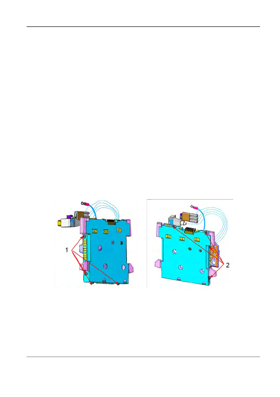
2. Remove the eight Phillips pan-head screws (M3) (with four sides and two on each side) of the
rotating disk cover, and remove the rotating disk cover.
1 Four Phillips pan-head screws (M3)
2 Two Phillips pan-head screws (M3)
3. Remove the two Phillips pan-head screws of the ground terminal on the up and down sides and
take off the up and down ground terminals.
Remove the two Phillips pan-head screw of the HDMI plug and take off the HDMI plug.
Remove the three cable ties and take off the power and signal terminals.
Diagnostic Ultrasound System
Service Manual
7 FRU Replacement
 Loading...


