Revision:1.0(2023-01-12)
42
2.3 Product Principle
2.3.1 Overall Architecture of Hardware System
22..33..11..11 Hardware System Diagram
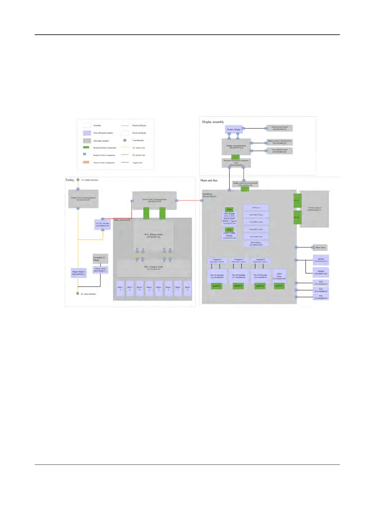
Figure2–1 Block Diagram of the Overall Hardware System Architecture
The hardware system of the TEX series product is divided into four units: frontend unit, backend
unit, power supply unit, and UI unit. The connection relationship between the four units and the
modules they contain are shown in the figure above.
• Frontend unit:
The frontend unit performs scanning for the ultrasonic imaging system and transmits the
imaging data collected from the scanning step to the backend unit for post-processing. Taking
the main board as the core, the frontend unit integrates the transmitting, receiving, PHV, CW,
TEE, and ECG functions and connects to the probe through the probe board.
• Backend unit:
The backend unit uses the main board as the carrier to mount the CPU and GPU modules. Its
main control module is CPU. It supports GPU for the supplement of post-processing
operations, as well as the control and monitoring of the whole system.
• Power supply unit of the trolley:
Diagnostic Ultrasound System
Service Manual
2 Product Knowledge
 Loading...


