Revision:1.0(2023-01-12)
47
• Receiving and caching of beam data
• Image pre-processing in each mode
• Data upload to the backend unit
7. Execution of front-end module reset, online upgrade, and module information management.
8. Probe-related control and management.
• High-voltage switch control
• CPLD configuration on the probe board
• SPI communicating with the probe board
9. Communication and control for image scanning-related accessories, including the following
accessories:
• CW/TEE driving function module
• Physiological signal function module
10.Distributed acoustic power testing signals: Acoustic power testing is output from FPGA to the
socket in the main board.
11.Integrated PHV output module.
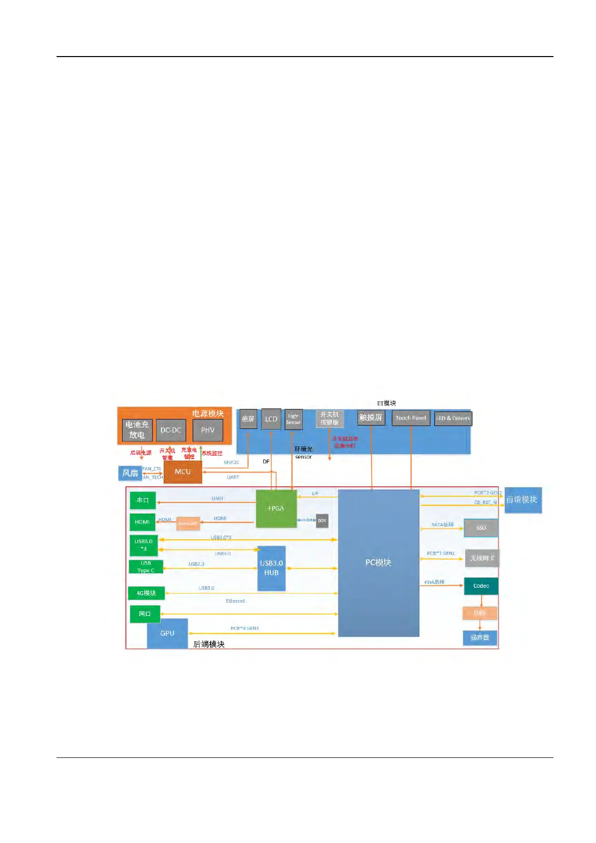
22..33..44..33 Backend of the Main Board
Figure2–6 Block diagram of the main board back end
The frontend board has the following functions:
• Support for the upgrade and improvement performance of the COME module.
• Support for the GPU module (with AI-related function implemented) of the MXM3.1 Type A
port.
Diagnostic Ultrasound System
Service Manual
2 Product Knowledge
 Loading...


