Revision:1.0(2023-01-12)
244
Protect the exterior surface of the parts.
Tools Required
Art knife, crosshead screwdriver (M4), flatheaded screwdriver, and socket head wrench (M5)
Fixtures Required
None
Specific Steps
1. Refer to the disassembly procedures in 7.2.2 Disassembly and Assembly, the section of
removing the main unit box, 7.22.2
Disassembly and Assembly, 7.23.2 Disassembly and
Assembly
, 7.30.2 Disassembly and Assembly, and 7.28.2 Disassembly and Assembly, and take
off each assembly.
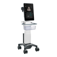
2. Take off the left and right damping axis cover of the main unit support.
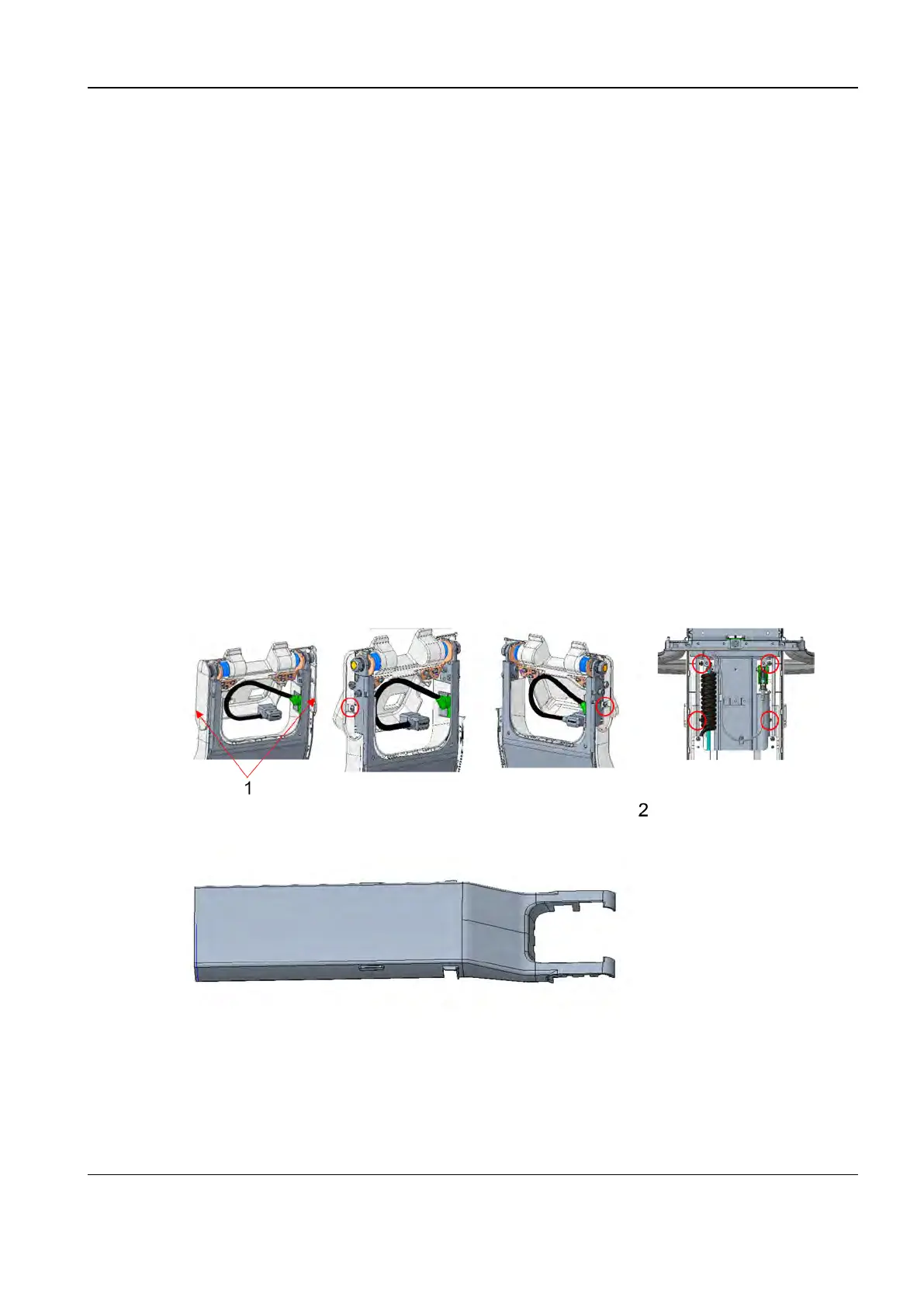
3. Use a crosshead screwdriver to remove the six M4X12 Phillips pan-head screws that connect
the front housing for upper column, so as to take off the front housing for upper column.
1 Damping axis cover
2 Six M4X12 Phillips pan-head screws
Diagnostic Ultrasound System
Service Manual
7 FRU Replacement