11 - 20
11.4 Communication Monitor
11.4.3 Screen display content
(1) Connection status of the communication ports
Indicates the connection status of Standard I/F-1 and I/F-2.
Listed in the table below are display items and the connection status (channel number).
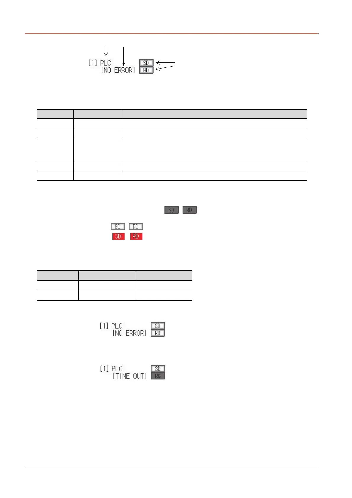
(2) Communication status
Displays the communication status of each communication port.
The SD and RD symbols appear in black on gray ( , ) while data are not being sent or received.
While data are being sent or received, the SD and RD symbols appear as follows.
GT2103: in black on white ( , ).
GT2104-R: in white on red ( , ).
They may appear lit depending on the communication status.
The SD and RD symbols on the screen indicate normal communication or cable disconnection.
Setting example
(a) [During normal communication (with connection to a device that supports the transparent mode)]
The SD and RD of the I/F-1 flash.
(b) [When the connecting cable with the controller is disconnected]
Only the SD of the I/F-1 flashes.
Display item Channel number Remark
PLC Ch1 "PLC" appears when connected to a controller (PLC or microcomputer)
BCR Ch8 "BCR" appears when connected to a barcode reader or RFID
TRANS. Ch9
"TRANS." appears when the controller that is allocated to one of the communication
ports supports the transparent mode
"TRANS." automatically changes to "PC" when communicating with drawing software
PC Ch9 "PC" appears when connected to a screen design software.
PRT ChA Appears when connected to a printer.
Port Channel number Controller type
I/F-1 Ch1 MELSEC-FX
I/F-2
Ch8
, Ch9
-
(1) (3)
(2)

 Loading...


