Home
Olympus
Laboratory Equipment
RollerFORM
Olympus RollerFORM User Manual
5
of 1
of 1 rating
168 pages
Give review
Manual
Specs
To Next Page
To Next Page
To Previous Page
To Previous Page
Loading...
DMT
A-20073-0
1EN, Rev
.
C, November 201
5
Chapter 6
106
Figure
6-33
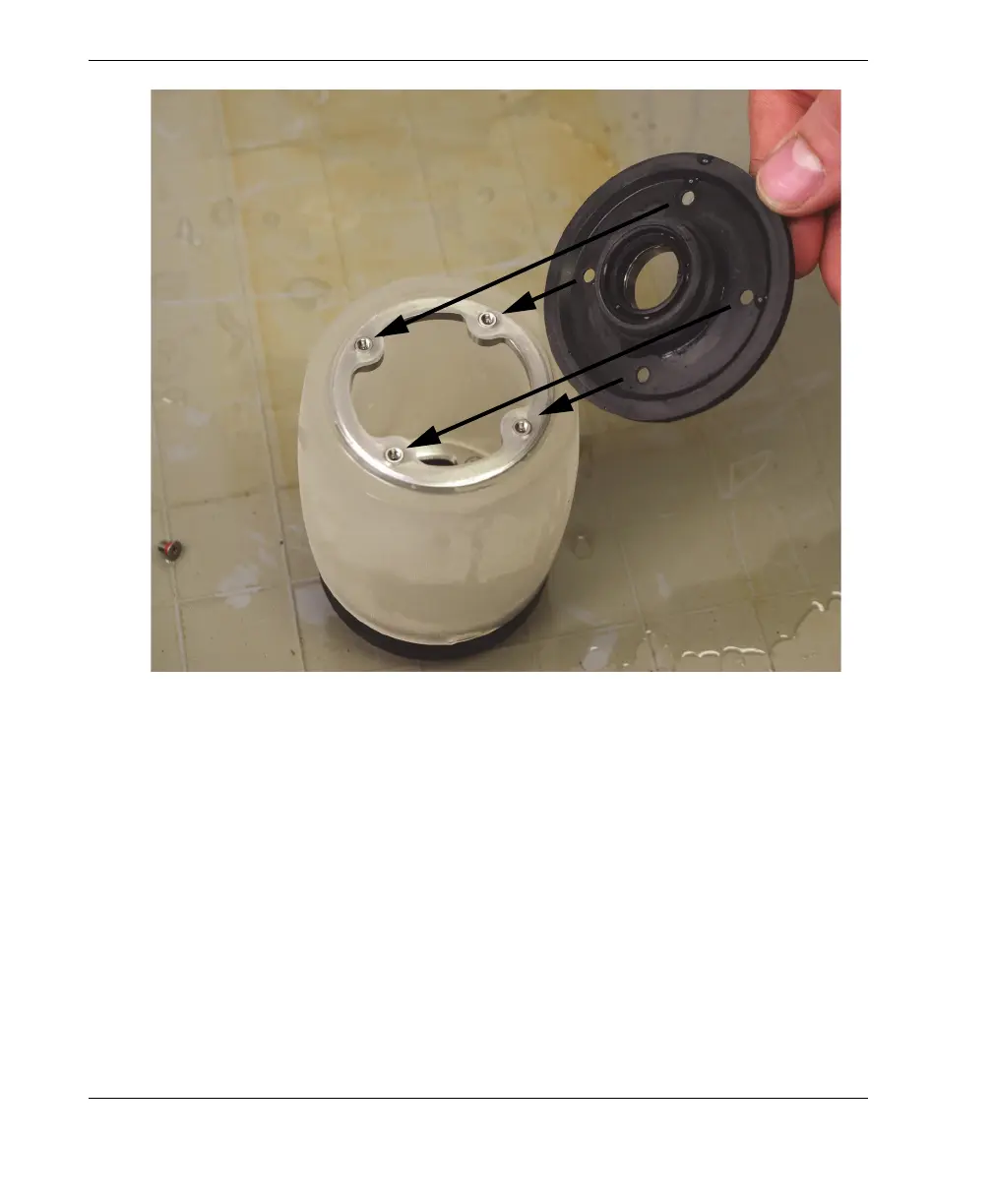
Installing the plain f
lange
b)
Install the four screws and their gasket
s in the plain flange, and then, using a
cross pattern, tighten the screws, first li
ghtly
, and then tightly (see Figure
6-34
on page
107).
111
113
Table of Contents
Table of Contents
3
Default Chapter
7
Figure I-1 Labels on the Rollerform
7
Labels and Symbols
7
Figure I-2 Label and Symbols on the Mini-Wheel Encoder
8
Table 1 Symbols
8
Important Information - Please Read before Use
11
Intended Use
11
Instruction Manual
11
Instrument Compatibility
12
Table 2 Ancillary Equipment
12
Repair and Modification
13
Presence of Visual Interferences
13
Safety Symbols
13
Safety Signal Words
14
Note Signal Words
15
Safety
15
Warnings
16
Equipment Disposal
17
CE (European Community)
17
WEEE Directive
17
EMC Directive Compliance
18
FCC (USA) Compliance
18
ICES-001 (Canada) Compliance
18
Warranty Information
19
Technical Support
19
Figure I-3 the Rollerform Scanner
21
Introduction
21
1 Rollerform Scanner Overview
23
Figure 1-1 the Contents of the Rollerform Case
23
Rollerform
24
Acoustic Wheel
25
Figure 1-2 the Rollerform Components
25
Figure 1-3 Acoustic Wheel Components
26
Wheels
27
Figure 1-4 Underside of Rollerform, Showing the Three Wheels and Encoder
28
Manual Pump
29
Figure 1-5 the 1.0 L Manual Pump and Feeding Tube
30
Figure 1-6 the Feeding Tube Valve in the Closed Position
31
Figure 1-7 the Manual Pump Piston and Trigger Mechanism
32
2 Setting up the Instrument
35
Connecting the Rollerform Scanner to the Instrument
35
Figure 2-1 an Omniscan Instrument with Rollerform Cables Connected
36
Setting up the Instrument
37
Figure 2-2 Unidirectional Scan
38
Setting up the Indexer Clicker
39
Figure 2-3 Bidirectional Scan
39
Figure 2-4 the Indexer Clicker on the Top Left-Hand Side of the Rollerform Handle
40
Setting up the Start Acquisition Button
42
Figure 2-5 Index Value in Omniscan
42
Figure 2-6 the Start Acquisition Button on the Top Right-Hand Side of the Rollerform Handle
43
3 Preparing the Rollerform Liquid Chamber
45
Filling the Acoustic Wheel's Liquid Chamber
45
Choosing a Liquid to Fill the Chamber
45
Filling the Liquid Chamber
46
Figure 3-1 the Open out Valve on the Flange
48
Figure 3-2 Connecting the Feeding Tube Adaptor to the in Check Valve
49
Figure 3-3 the Feeding Tube Valve in the Open Position
50
Figure 3-4 the Manual Pump Piston
51
Removing Air Bubbles from the Liquid Chamber
53
Figure 3-5 Measuring the Gap between the Acoustic Wheel Flange and the Surface
53
4 Preparing for an Inspection
55
Applying Couplant to the Acoustic Wheel and the Surface to Inspect
55
Optimizing the Phased Array Signal
56
Figure 4-1 Adjusting the Probe Angle to Optimize the Signal
57
Adjusting the Middle Wheel
58
Retracting the Middle Wheel
58
Figure 4-2 Unlocking the Middle Wheel
59
Removing the Middle Wheel
60
Figure 4-3 Locking the Middle Wheel
60
Adjusting the Middle Wheel for Convex Surface Axial Scans
61
Figure 4-4 Unlocking the Middle Wheel
61
Figure 4-5 Unlocking the Middle Wheel
62
Figure 4-6 Keeping both Rollers in Contact with a Convex Surface
63
Figure 4-7 Keeping both Rollers or the Skid Plate in Contact with a Narrow Surface
64
Tracing the Scan Guide Lines on the Surface to Inspect
65
Figure 4-8 Locking the Middle Wheel
65
Figure 4-9 Drawing Parallel Lines on the Surface to Inspect
67
5 Performing an Inspection
69
Figure 5-1 Engravings on Top of Rollerform Frame
70
Figure 5-2 Arrow on the Probe-Axle Indicating the Direction from First to Last Element on the Probe
71
Figure 5-3 the Laser On/Off Button on Top of the Laser Casing
72
Figure 5-4 Positioning the Rollerform on the First Guide Line
73
Figure 5-5 the Start Acquisition Button Location
74
Figure 5-6 Positioning the Rollerform on the Next Guide Line
75
Figure 5-7 the Indexer Clicker Location
76
6 Maintenance
77
Removing the Acoustic Wheel from the Rollerform Scanner
77
Figure 6-1 Removing the Probe Angle-Adjustment Components
78
Figure 6-2 Removing the Acoustic Wheel's Holding Brackets
79
Emptying the Acoustic Wheel's Liquid Chamber
80
Figure 6-3 Removing the Acoustic Wheel
80
Figure 6-4 the Location of the out Valve
82
Changing the Probe-Axle
83
Removing the Probe from the Acoustic Wheel
83
Figure 6-5 Emptying the Liquid Chamber
83
Figure 6-6 Removing the Bushing from End of the Probe-Axle
84
Figure 6-7 Removing the External Retaining C-Clip from the End of the Probe-Axle
85
Installing the Probe in the Acoustic Wheel
86
Figure 6-8 Pushing the Probe-Axle out of the Acoustic Wheel
86
Figure 6-9 Inserting the Probe-Axle Inside the Acoustic Wheel
87
Figure 6-10 Installing the External Retaining C-Clip on the Probe-Axle End
88
Figure 6-11 Pushing the C-Clip in the Groove on the Probe-Axle End with the C-Clip Installation Tool
89
Figure 6-12 Pushing the C-Clip in the Groove on the Probe-Axle End with the C-Clip Installation Tool
90
Cleaning the Liquid Chamber
91
Figure 6-13 Probe Cable Extending from the Front to the Rear End of the Rollerform Handle
91
Figure 6-14 Removing the Acoustic Wheel Flange's External Retaining Screws
93
Figure 6-15 Removing the Acoustic Wheel Plain Flange
94
Figure 6-16 Installing the Plain Flange
95
Preserving or Restoring the Tire's Transparency
96
Preserving the Tire's Transparency
96
Figure 6-17 the Location of the out Valve
97
Restoring the Tire's Transparency
98
Figure 6-18 Emptying the Liquid Chamber
98
Figure 6-19 Removing the Plain Flange's External Retaining Screws
99
Figure 6-20 Removing the Acoustic Wheel Plain Flange
100
Figure 6-21 Installing the Plain Flange
101
Changing the Tire
102
Figure 6-22 Installing the Plain Flange's External Retaining Screws
102
Figure 6-23 the Stainless Steel Rings that Hold the Flanges to the Tire
103
Figure 6-24 Removing the Plain Flange's External Retaining Screws
104
Figure 6-25 Removing the Acoustic Wheel Plain Flange
105
Figure 6-26 Accessing the Captive Screws of the Flange with the Liquid-Control Valves from Inside the Liquid Chamber
106
Figure 6-27 Pushing a Ring out of Its Retaining Groove
107
Figure 6-28 Removing a Ring out of the Tire
107
Figure 6-29 Inserting a Ring in the Tire
108
Figure 6-30 Installing a Ring in Its Retaining Groove in the Tire
109
Figure 6-31 Installing the Flange with the Liquid-Control Valves
110
Figure 6-32 Tightening the Captive Screws of the Flange that Contains the Liquid-Control Valves from Inside the Liquid Chamber
111
Figure 6-33 Installing the Plain Flange
112
Installing the Acoustic Wheel on the Rollerform Scanner
113
Figure 6-34 Installing the Plain Flange's External Retaining Screws
113
Figure 6-35 Installing the Bushing on the End of the Probe-Axle
114
Figure 6-36 Installing the Acoustic Wheel Holding Brackets
115
Changing the Mini-Wheel Encoder
116
Figure 6-37 Installing the Probe's Angle-Adjustment Components
116
Removing the Mini-Wheel Encoder from the Rear Roller
117
Figure 6-38 Cutting the Cable Tie off the Rollerform Handle
117
Figure 6-39 Removing the Screws from the Rollerform Handle
118
Figure 6-40 Loosening the Rear Roller's Retaining Screw
119
Figure 6-41 Pushing Loose the Rear Roller's Axle from Its Seat
120
Figure 6-42 Sliding out the Rear Roller's Axle
121
Figure 6-43 Loosening the Encoder Retaining Screw
122
Figure 6-44 Removing the Mini-Wheel Encoder
123
Removing the Mini-Wheel Encoder from the Alternate Encoder Holder
124
Figure 6-45 the Mini-Wheel Encoder Installed on the Alternate Encoder Holder
124
Figure 6-46 Removing and Pivoting the Alternate Encoder Holder 90
125
Figure 6-47 Tightening the Screw of the Alternate Encoder Holder
126
Installing the Mini-Wheel Encoder on the Rear Roller
127
Figure 6-48 Tightening the Encoder Retaining Screw
128
Figure 6-49 Aligning the Rear Roller's Axle-End Flat Bevel with the Retaining Screw
129
Figure 6-50 Installing the Handle Cap on the Rollerform's Handle
130
Relocating the Mini-Wheel Encoder on the Acoustic Wheel
131
Figure 6-51 Installing the Cable Sheath and the Cable Tie
131
Figure 6-52 Loosening the Rear Roller's Retaining Screw
132
Figure 6-53 Pushing Loose the Rear Roller's Axle from Its Seat
133
Figure 6-54 Sliding out the Rear Roller's Axle
134
Figure 6-55 Loosening the Encoder Retaining Screw
135
Figure 6-56 Removing the Mini-Wheel Encoder
136
Figure 6-57 Aligning the Rear Roller's Axle-End Flat Bevel with the Retaining Screw
137
Figure 6-58 Loosening the Screw of the Alternate Encoder Holder
138
Figure 6-59 Removing and Pivoting the Alternate Encoder Holder 90
139
Figure 6-60 the Mini-Wheel Encoder Installed on the Alternate Encoder Holder
140
6.10 Changing the Laser Batteries
141
Figure 6-61 Changing the Batteries in the Laser
141
6.11 Adjusting the Angle of the Guiding Laser Beam
142
Figure 6-62 Aligning the Guiding Laser Beam
143
7 Specifications
145
General Specifications
145
Environment Specifications
145
Table 3 General Specifications
145
Connector Reference
146
Table 4 Operating Environment Specifications
146
Table 5 Required Encoder Cable Adaptor
146
Figure 7-1 LEMO Connector Pinout Diagram for EWIX1439 Cable Family
147
8 Spare Parts
149
Rollerform Spare Parts Kits
149
Figure 8-1 Rollerform - Exploded View
150
Table 6 Rollerform Spare Parts
150
Manual Pump Spare Parts Kit
152
Figure 8-2 Manual Pump Spare Parts (P/N: ROLLERFORM-A-PUMP [Q7790006])
153
Table 7 Manual Pump Spare Parts
153
List of Figures
155
List of Tables
159
Index
161
5
Based on 1 rating
Ask a question
Give review
Questions and Answers:
Need help?
Do you have a question about the Olympus RollerFORM and is the answer not in the manual?
Ask a question
Olympus RollerFORM Specifications
General
Brand
Olympus
Model
RollerFORM
Category
Laboratory Equipment
Language
English
Related product manuals
Olympus U-RFLT50
36 pages
Olympus U-SDO3
40 pages
Olympus OER-Pro
308 pages
Olympus SZ2-STS
12 pages
Olympus DP2-SAL
108 pages
Olympus U-LH50HG
36 pages
Olympus ENDO-AID
10 pages
Olympus SZ2-STB1
12 pages
Olympus U-HGLGPS
20 pages
Olympus OER-Elite
138 pages
Olympus SZX2 Series
16 pages
Olympus VISERA CLV-S40
82 pages