DMTA-20073-01EN, Rev. C, November 2015
Chapter 5
68
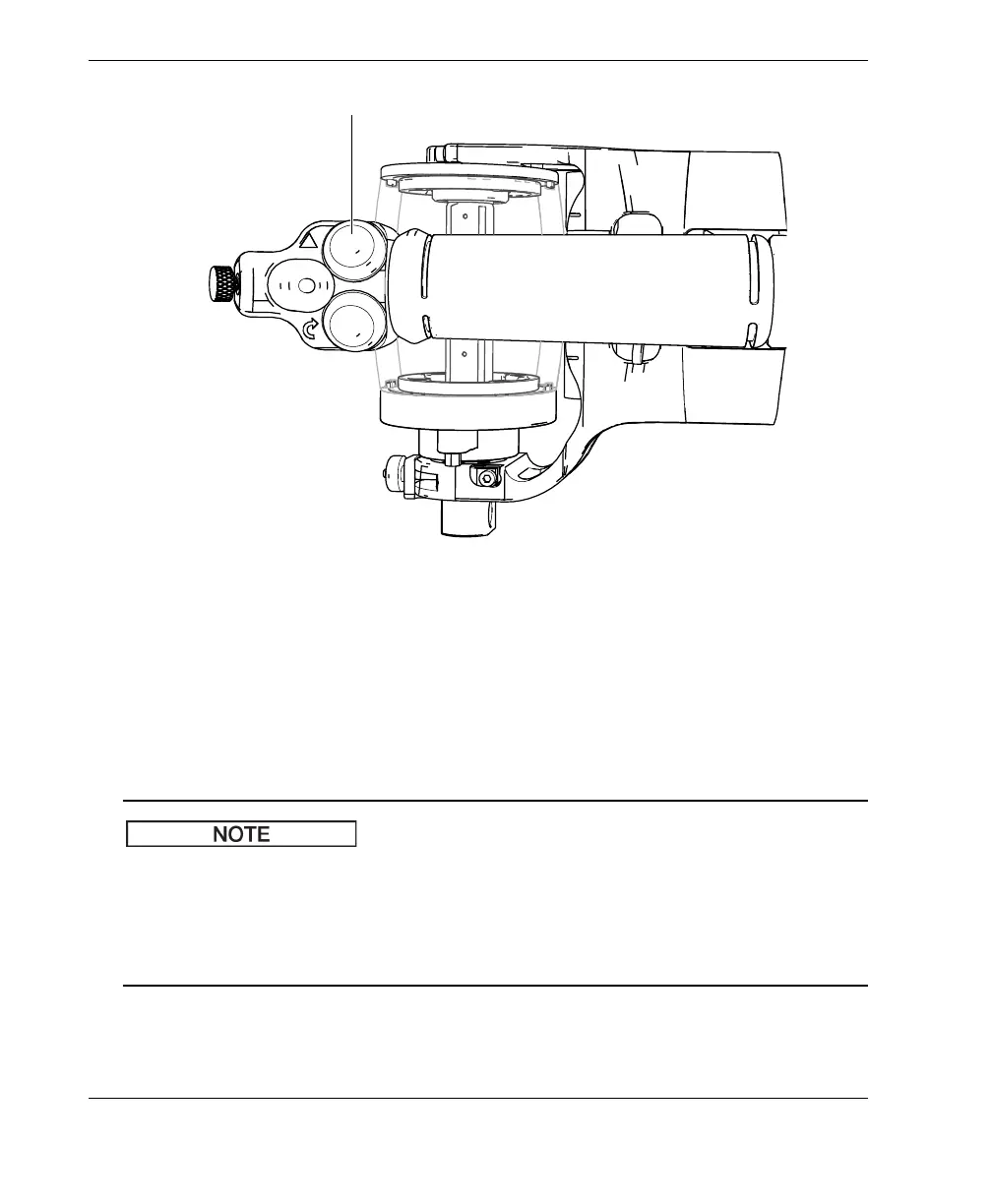
Figure 5-5 The Start Acquisition button location
9. Roll the RollerFORM on top of the guide line, making sure the guiding laser beam
is perfectly aligned with the drawn guide line for the entire duration of the scan
pass.
10. At the end of the area to inspect, immobilize and lift the RollerFORM, making
sure that the wheel on the Mini-Wheel encoder does not turn.
On the RollerFORM, the first element of the probe is located on the right-hand side of
the scanner, when you are holding it with the acoustic wheel furthest away from you.
Series of scans must always be performed with the laser guide aligned to the drawn
guide lines, and from right to left. Thus, indexing is done by moving the scanner to
the next guide line on the left.
11. Return the RollerFORM to the start of the area to inspect, positioning it over the
next guide line to the left. Using the laser beam, align the RollerFORM precisely
with this guide line (see Figure 5-6 on page 69).
 Loading...