3-1SectionScreen Creation Procedure
288
3-1 Screen Creation Procedure
Follow the procedure shown below to create screens for the NT21,
NT31/NT31C, and NT631/NT631C.
The following gives the procedure assuming that the setting for the PT has been
completed. The operating procedure for a Support Tool is not given here. For the
operating procedure for the Support Tool, refer to the NT-series Support Tool
Version 4. for Windows Operation Manual (V061-E1-).
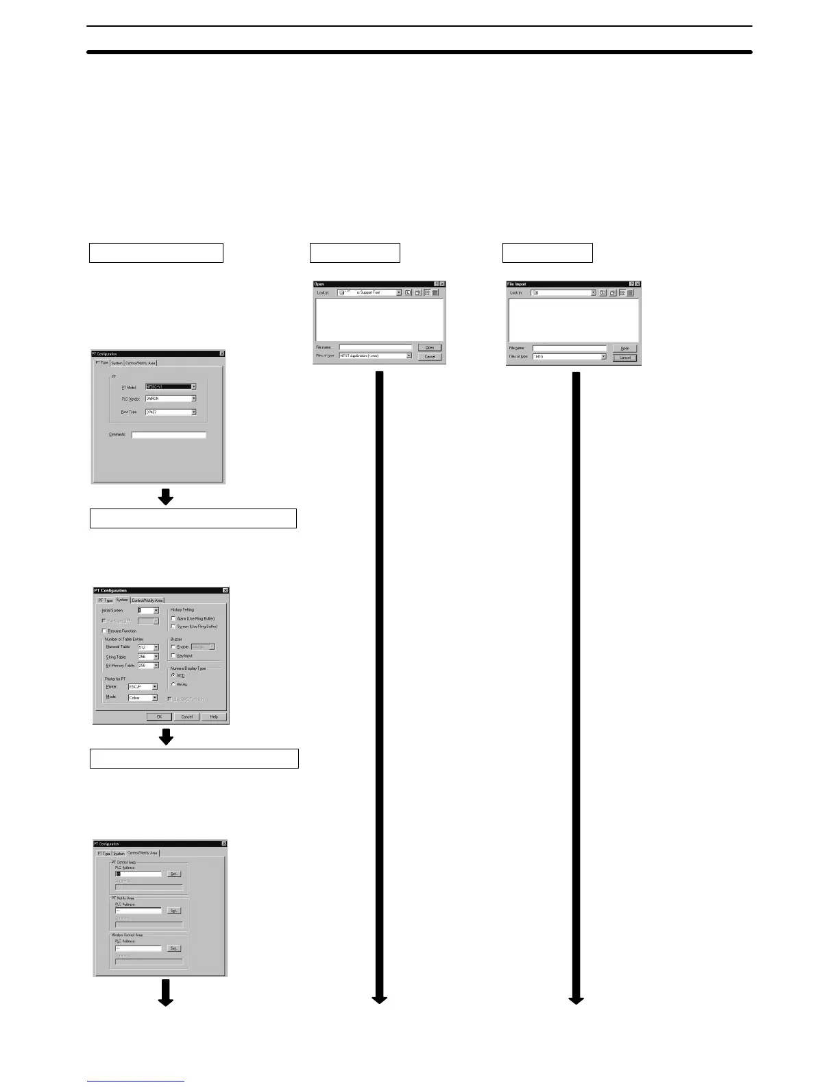
Designate a work file.
Creating a New Screen
Tool Setting (PT model)
Set the PT model as follows:
NT21: Set NT21.
NT31: Set NT31-V2.
NT31C: Set NT31C-V2.
NT631: Set NT631-V2.
NT631C: Set NT631C-V2.
System Setting (Memory Switch Setting)
Set the memory switches that determine the
basic operation of the PT.
The numeral/character string/bit memory table
entry settings should also be made at this stage.
Setting for PT Status Control/Notify Area
Allocate words for the PT status control area
and PT status notify area, necessary for the
direct connection function, in the host.
For details, refer to 2-2 Areas for
Control/Notification (page 52).
Correcting an Existing File
File Designation
Importing DOS Version Data
File Designation
Designate the work file to be data converted.
NT-series Support Tool
NT-series Support Tool

 Loading...


