4-2SectionOutline of Communications
372
4-2 Outline of Communications
This section describes the basic communication protocol when using memory
link and the program flow for using memory link, taking RS-232C communica-
tions using the BASIC language as an example.
4-2-1 Communication Protocol
Communication between the host and the PT takes place in accordance with the
following protocol.
1, 2, 3... 1. In order to perform communications, it is necessary to open the communica-
tion line. Opening here means making the line usable.
2. In accordance with the commands, the PT is controlled or notification is re-
ceived from the PT.
3. To terminate communication, close the communication line.
[Host program]
OPEN instruction
PRINT #instruction
LINE INPUT
CLOSE instruction
Line opened
Command
transmission
Line closed
#instruction
Command/
response
transmission
Command/
response
transmission
Command
reception
Communication line
Open state
[Operation at PT]
:
:
:
:
:
Once the line has been opened, it can be used until it is closed.
Function of Each Command
OPEN command: Opens the RS-232C line.
Also sets the communication conditions at the host
side. Refer to the Setup Manual for details.
PRINT # command: Sends commands to the PT via an RS-232C line.
LINE INPUT # command: Receives the command or response from the PT.
In order to receive input delimited by commas and
double quotation marks, use LINE INPUT.
CLOSE command: Closes the RS-232C line.
For detailed information on commands, refer to the BASIC language command
manual for the host.
Operation When Using Commands
The flow of communications between the host and the PT follows one of the
three patterns indicated below, depending on the types of command and the set-
tings made for response with the memory switches. Refer to section 6 of the Set-
up Manual for details.
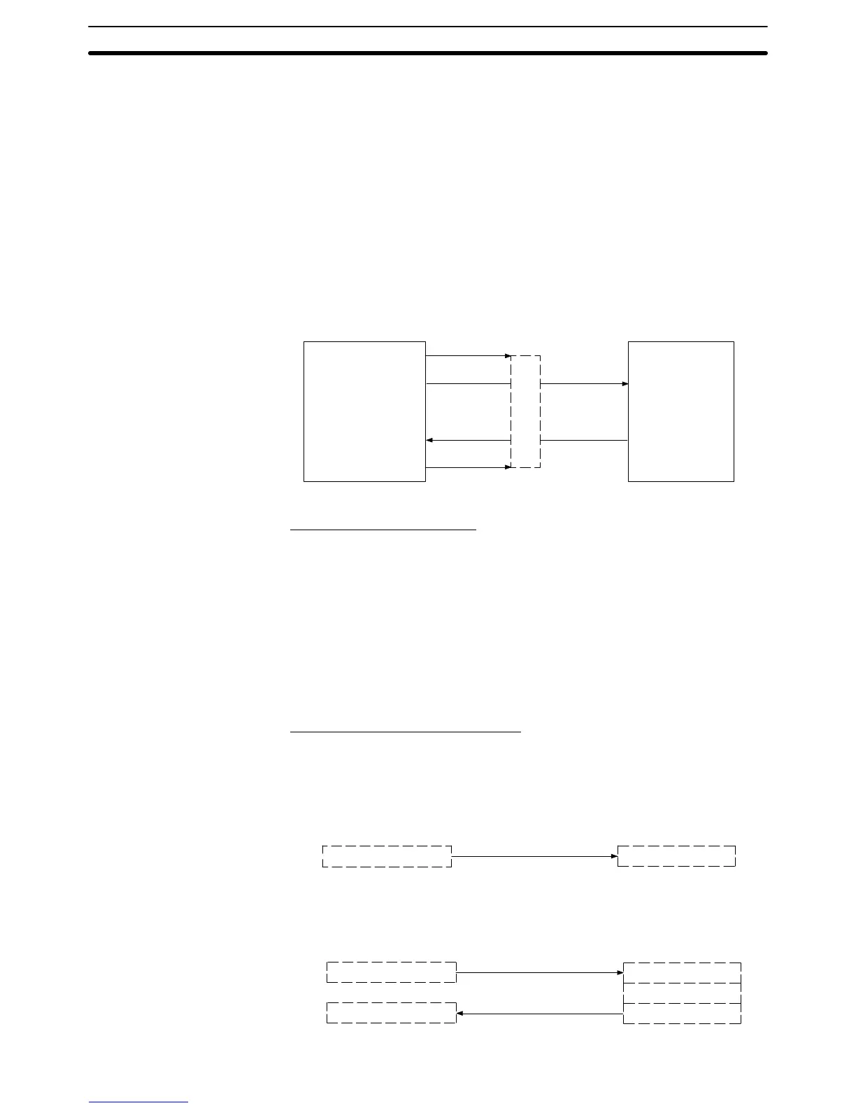
• Pattern with write command when No is set for the response
Command transmission
[Operation at host]
Data write command
Command processing
[Operation at PT]
However, when an error occurs, an error response is returned.
• Pattern with data read command, re-send command, and data write command
when response Yes is set.
[Operation at host]
Data write command
Command transmission
Command reception
Command processing
Response transmission
Command/response
reception
Response or re-send command
[Operation at PT]