3-3SectionScreen Display and Notification
303
Setting
1, 2, 3... 1. When creating a screen with the Support Tool, set the bit memory table entry
as indicated below and allocate a bit for the bit memory table entry in the
host.
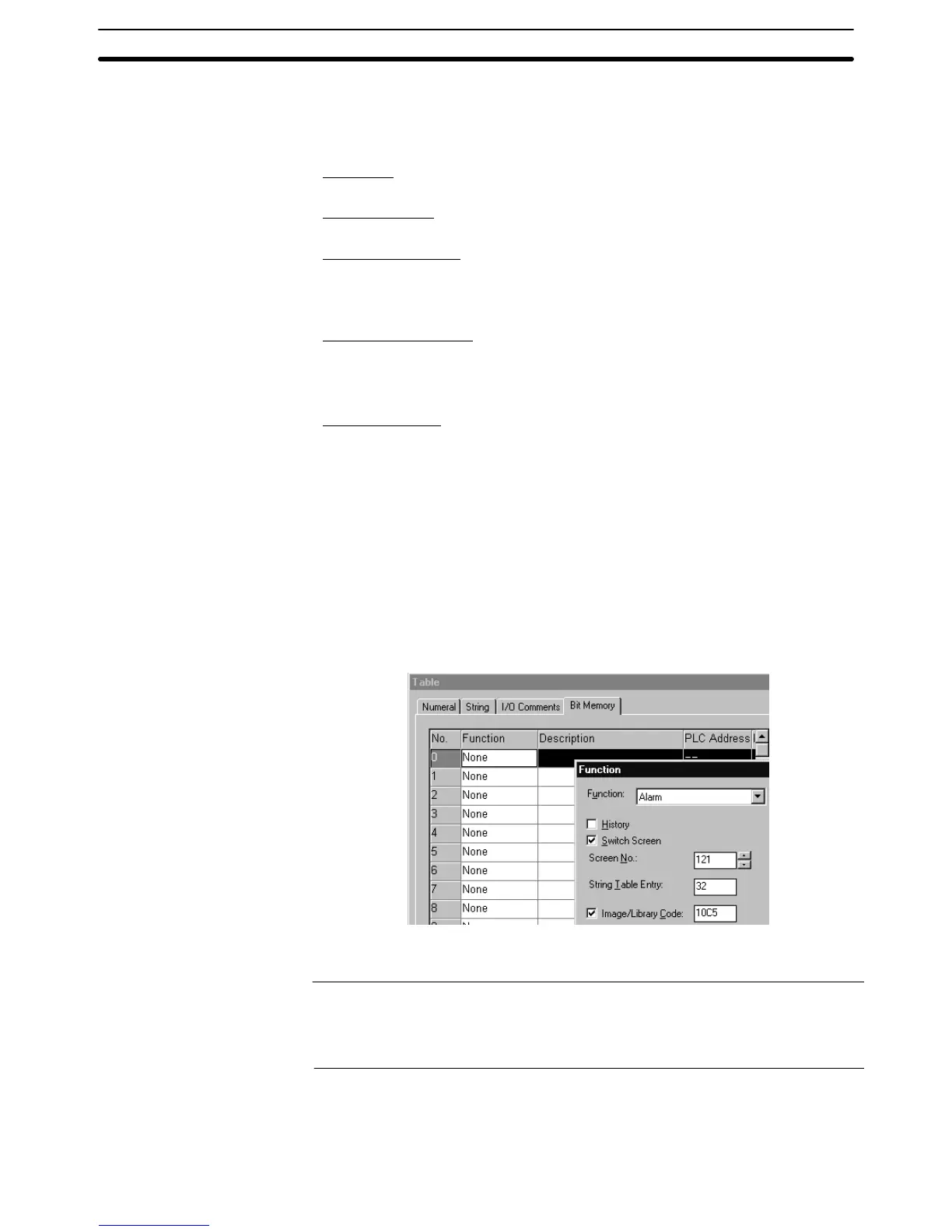
Function:
Alarm (Alarm list/history function)
Switch Screen:
Check mark set
String Table Entry:
Table entry number of the character string memory table entry where the mes-
sage to be displayed when the bit is 1 (ON) is stored.
• 0 to 1999
Image/Library Code:
Code of the image data/library data that is displayed when the bit is 1 (ON).
• 0001 to 0FFF
H: Image data
• 1000 to 3FFF
H: Library data
Screen number:
Screen number of the screen that corresponds to the 1 (ON) bit in the bit memory
table entry (in the host).
• 0001 to 3999: Screen No. 1 to No. 3999
• 9001: Occurrence history screen
• 9002: Frequency history screen
• 9020: Programming Console function screen
• 9021 to 9023: Device Monitor function screens (NT31/NT31C or
NT631/NT631C only)
• 9030: Brightness and contrast adjustment screen (NT31/NT31C or
NT631/NT631C only)
• 9999: Return to the previous screen
For details of the setting for bit memory table entries, refer to 2-3-3 Bit Memory
Table (page 83).
Reference: To display overlapping screens, specify the screen number of the parent
screen.
The screen is not switched if elements have not been registered to the speci-
fied screen number.
2. When creating the screen, register an alarm list/history element for it.
For details of the alarm list/history, refer to 2-11 Alarm List, Alarm History
(page 182).