Setting up Compax3
C3I12T11
192-120113 N08 C3I12T11 - December 2010
4.1.10. Operating mode / I/O assignment
In this chapter you can read about:
I/O assignment for control via the Compax3 inputs/outputs ............................................134
I/O assignment, control word and status word with control via COM port .......................135
The operating mode defines the I/O assignment of the Compax3 I/Os.
4.1.10.1 I/O assignment for control via the Compax3
inputs/outputs
If control is not made via RS232 / RS485, an M - option (M10 or M12) will be
required. The assignment of the inputs and outputs is fixed.
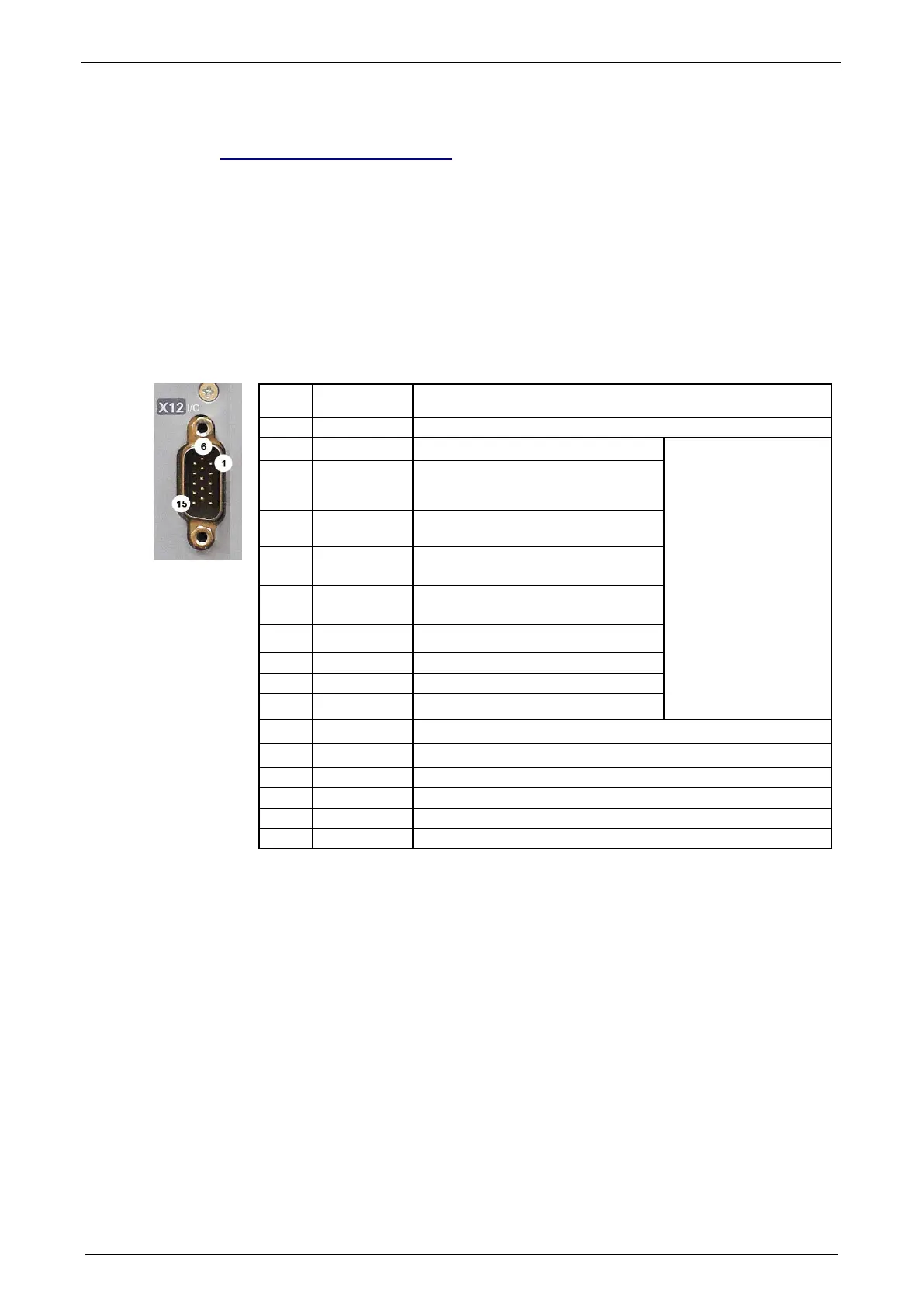
Assignment of the intra-device inputs and outputs
1 O +24 V DC output (max. 400mA)
2 O0 No Error
Only for "fixed
assignment"
Functions are
available, if "Fixed
assignment" was
selected for the I/O
assignment in the
configuration wizard
3 O1 Position / speed / gear synchronization
attained (max. 100 mA)
4 O2 Power stage without current (max.)
100 mA)
5 O3 Axis energized with a setpoint of 0
(max. 100 mA)
6 I0="1": Quit (positive edge) / Axis enable
I0="0" Axis disable with delay
7 I1 no Stop
8 I2 JOG +
9 I3 JOG -
10 I4 Reg input
11 I 24V input for the digital outputs Pins 2 to 5
12 I5 Limit switch 1
13 I6 Limit switch 2
14 I7 Machine zero initiator
15 O GND24V
All inputs and outputs have 24V level.
Maximum capacitive loading of the outputs: 30nF (max. 2 Compax3 inputs can be
connected)
Input-/Output extension (see on page 134)
The display of the digital inputs in the optimization window of the C3 ServoManager
does not correspond to the physical status (24Volt=on, 0Volt=off) but to the logic
status: if the function of an input or output is inverted (e.g. limit switch, negatively
switching), the corresponding display (LED symbol in the optimization window) is
OFF with 24Volts at the input and ON with 0 Volts at the input.
Optimization
window display

 Loading...


